Ad Widget

Collapse

Announcement

Collapse
No announcement yet.

Taming a Gibson tone stack

Collapse
X
 
  • Filter
  • Time
  • Show
Clear All
new posts

  • Taming a Gibson tone stack

    I'm doing standard 50-year repairs on a customer's 1965 Gibson Skylark GA-5, but, in stock form, the amp's tone is fairly annoying. Strumming the guitar produces a fizzy sound like someone playing a zither that sits atop the rest of the signal, probably a result of the bass control that's bypassed by a 500pF capacitor to prevent excessive treble losses.

    I ran a couple of experiments based on increasing Miller capacitance and a technique I've seen used in Leslie amps and a few others (capacitor across the output tube plates). A 10pF cap between the plate and grid of the second 12AU7 stage in combination with a 1,000pF capacitor of sufficient voltage rating across the EL84 plates seems to get rid of that fizziness while leaving plenty of natural-sounding high end. (I like treble-cut circuits that also reduce any tendency to ultrasonic oscillation, especially in an amp like this with no global NFB.)

    Is there a better way to tweak this kind of Gibson tone stack, or does this relatively simple mod sound like a good idea?

    On another site, I read of someone inserting a 50k pot between C4 and ground and dialing in ~36k to prevent excessive loss of mids via the bass control.

    Click image for larger version

Name:	George's Skylark.jpg
Views:	2
Size:	629.5 KB
ID:	869170

  • #2
    I wouldn't expect anything about the tone shaping to cause fizziness.
    The cap from plate to grid is something I've done. It's very effective. Small values are best and IME it prevents instability when used instead of a shielded cable on an input. So that criteria is covered as well.
    The cap across the plates of the power tubes is usually done in series with a resistor valued a little over the primary impedance of the OT. Also IME a 1500p cap and a 10k resistor will squash any spikes and not round over the edge of the waveform terribly. Using just the cap causes the tubes to see a dead short at frequencies above the knee. Since these would be the spike frequencies, and prone to voltages double or more B+, it's probably better to dissipate as much as possible with a resistor. JM2C on that.
    I don't know any mods for that specific amp. Assuming any remaining fizziness still isn't being caused by tone shaping circuits I would next look to crossover distortion caused by bias shift in the cathode resistance. Check to see that the resistor hasn't drifted high. It it's ok you could add a 3W zener across the resistor. Measure the voltage at the cathode. Your zener voltage should be two or three volts higher. This will eliminate excessive voltage rise that cools the bias and can cause crossover distortion when clipping.
    "Take two placebos, works twice as well." Enzo

    "Now get off my lawn with your silicooties and boom-chucka speakers and computers masquerading as amplifiers" Justin Thomas

    "If you're not interested in opinions and the experience of others, why even start a thread?
    You can't just expect consent." Helmholtz

    Comment


    • #3
      Thanks, Chuck.

      I've seen the capacitor across the output tube plates done both ways, both with and without series resistors. Leslie did it with capacitors alone from the 1940s through around 1961. Hammond used 1,000pF caps across 6V6 plates in M3 organs, then switched to 10k/2,200pF at some point in production, continuing this into the M100 series. Leslie used 1,600V caps for this application, and I use 2,000V rated caps when I replace them.

      Comment


      • #4
        And I would hope that you proved that it is not the speaker.

        Comment


        • #5
          I like to leave things like this alone and then go back and listen a second time. I now think that a 10pF cap on one of the 12AU7 sections is enough and that the EL84 plate caps are not needed. As Chuck suggested, it's probably a result of unshielded hookup wire. I do have some skinny teflon coax, so that might be another fix if I can isolate it to a particular run. I've had to do that before to quash oscillations.


          I eliminated the speaker :-) I have several extension cabinet options in the shop.

          Comment


          • #6
            I thought I'd post an update on this topic. The Skylark's original CTS speaker ended up needing to be reconed (buzzing), and, with a new cone, the speaker is now brighter, so I've been working with the owner (friend of mine) to tweak it to make the amp more user-friendly. I ended up completely (rather than partially) bypassing both 12AU7 stages to increase gain in the bass, and I put a 220k resistor in series with the 500pF cap on the upstream side. We also experimented with some mid boost and ended up with 100k between C4 and ground. It's a fairly versatile small amp now; you can dial in a number of useful sounds.

            These tweaks replaced those mentioned in my earlier post.

            In stock form, my opinion is that this Skylark is a pretty awful-sounding amp. I don't know what Gibson was thinking because it really didn't need to be. Were they trying to make amps sound as jangly as possible to go along with the British Invasion sound? Why build a circuit that rolls off bass in four different ways paired with minimal attenuation of the highs?

            Comment


            • #7
              Originally posted by Rhodesplyr View Post
              Why build a circuit that rolls off bass in four different ways paired with minimal attenuation of the highs?
              Crappy speakers?
              Originally posted by Enzo
              I have a sign in my shop that says, "Never think up reasons not to check something."


              Comment


              • #8
                Originally posted by g-one View Post
                Crappy speakers?
                Eh, the speaker is a CTS Alnico 10", not particularly different from the CTS or Oxford tens you find in all sorts of 60s Fender amps. Same 1" voice coil. Same seamed cone. It handles the additional bass with no problem.

                Comment


                • #9
                  Actually, a "crappy" speaker might get you the treble attenuation you need... feel free to send me that CTS!

                  I wonder if the amp was voiced for Gibson's guitars of the time. I'd imagine the guitar to be pretty dark... if they'd been sitting around playing a Tele through it, maybe they'd not have made it that way...

                  Justin
                  "Wow it's red! That doesn't look like the standard Marshall red. It's more like hooker lipstick/clown nose/poodle pecker red." - Chuck H. -
                  "Of course that means playing **LOUD** , best but useless solution to modern sissy snowflake players." - J.M. Fahey -
                  "All I ever managed to do with that amp was... kill small rodents within a 50 yard radius of my practice building." - Tone Meister -

                  Comment


                  • #10
                    Why build a circuit that rolls off bass in four different ways paired with minimal attenuation of the highs?
                    Are we talking about the schematic posted in the OP?
                    I see none of that.

                    As of "fizzy sound like someone playing a zither that sits atop the rest of the signal" that stinks of oscillation/instability or very poorly biased gain stage or poorly biased output tubes o very dead scratchy speaker or all of the above.

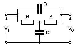
                    As of what they call "bass control" it's actually a Bridged T midrange killing one, and the effect is similar to having a F or M tone stack on full (fixed) with mids on 0 .
                    Run Duncan's TSC with the Gibson values.


                    The "bass control" actually bypasses that T notch network .
                    Juan Manuel Fahey

                    Comment


                    • #11
                      Originally posted by Justin Thomas View Post
                      I wonder if the amp was voiced for Gibson's guitars of the time. I'd imagine the guitar to be pretty dark... if they'd been sitting around playing a Tele through it, maybe they'd not have made it that way...
                      I think that this is the best explanation for the design--to make a Gibson guitar sound bright and jangly for a particular 1965 market.

                      Comment


                      • #12
                        Originally posted by J M Fahey View Post
                        Are we talking about the schematic posted in the OP?
                        I see none of that.
                        There's the input high-pass filter (0.0047uF/470k), the moderately-bypassed first stage (5uF/2.7k) and the incompletely-bypassed second stage (2uF/1k). Adjusting any of these by clipping in larger capacitors in parallel results in increased bass response.

                        As I wrote above, we added a 100k resistor between C4, the cap that kills the midrange, and ground. (I'm not the first person to try this.) Also, most of these 10" CTS or Oxford speakers have response peaks in the 1 to 2kHz range, so that works in combination with the resistor to flatten the midrange dip.

                        Comment

                        Working...
                        X