 Tweet
Tweet
Most of the drivers, I'm assuming, provide the logic and/or buffers for driving an LED array to provide a desired order of active segments. My experience with microcontrollers and non-tube amp ccts. is extremely limited. However, you can use a D-A converter (or even digital resistors that are controlled) from the microcontroller to control the brightness/intensity of an LED through other ccts.
-
-
As you can expect somebody has already figured it out /at least this is one way to do it/. Check out page 2:
http://home.comcast.net/~sbernardi/e...echo_delay.pdf
I guess RV1 and R33 can be omitted.Comment
-
It's a flock of about 22 or 24 of that VTL5C9 in those Preamps IIRC. And it's a pure nightmare, when they become older and are loosing their specs - and you try to find the 2 or 3 causer.Originally posted by Steve Conner View Post
Recently I've told an owner, that I either swap all inside, or none - another way I can't offer. He went off.
LarryThe fault almost always is sitting in front of the amp
Comment
-
I wish there was an easier solution for that but I can't figure it out at this time. Obviously digital pots are not an option. Maybe that's why you don't see many all tube programmable preamps these days.
Any other ideas are more than welcome.Comment
-
IIRC, transistors can be configured to multiply (and/or 'transfer') impedance/resistance. So, my guess is that if that is so than a cct. can be made from a stout enough transistor to handle what a tube needs, and serve as an intermediate device between the tube and the fragile digital resistors. I believe that a transistor can also be used as a passive device, and perhaps the behavior of the passive transistor can be manipulated by another cct. Just guessing here, because I don't know a lick about transistors.Comment
-
The triaxis uses TWO dual vactrols to replace a pot (I studied the patent, but my library is still down so I don't have the patent number handy).
Each pot is replaced by a 10-tap voltage divider with the values in the stack selected to replicate the upper/lower resisitances in the required pot. An analog multiplexer selects a tap in each stack, which then feeds a voltage into an op-amp. The op-amp drives the LED in a dual vactrol, and uses one of the resistor elements in its feedback loop. The other resistive element is the upper or lower pot element in the tube side of the circuit. Each potentiometer-connected pot (fender treble control) requires a PAIR of these lashups to act as upper and lower segments of the pot. A rheostat-connected pot (fender mid control) only needs one of these.
The patent covers using a mux-selected voltage divider tap, so using a DAC should not infringe.
I did some work to make a generic DAC-controlled version of these that would be scale with a resistor of the end-to-end value of the pot - again, my library is down. A 12-bit DAC would give you enough resolution to do linear, 10% and 20% audio and reverse audio tapers, and dual 12-bit DACs are easy to find.
Email me at das_float@yahoo.com to remind me to dig for my old files when I get my library going again.
Hope this helps!Comment
-
Did you mean something similar to the programmable gain /fig.10/:
http://optoelectronics.perkinelmer.c...oisolatorB.pdfComment
-
For the controller side, yes. The differences are that the Vactrols have dual INDEPENDENT LDR elements (4 resistor terminals) and that the _controlled_ side resistor gets hooked up like half a pot.Originally posted by Gregg View PostComment
-
Which part number exactly do you mean because I don't see any that coresponds to your description /I see only 3 terminal ones/?Comment
-
Oh - yeah - This was the project killer. Perkin-Elmer only does the 3-terminal ones these days. Mesa went to a Japanese company for their parts ... it will take me a while to remember the name ... I found their US rep, too - again remembering the name will take some doing.Originally posted by Gregg View Post
I'm supposed to get my library back tomorrow. Just hope that stuff was in there.
I thought about rolling my own - getting and matching CdS cells and packaging pairs with LEDs, but I'm not mechanical enough to guaratee matched illumination over two cells. Using 2 independent LED/photocell units with the LEDs in series looked like an answer, but the LED datasheets I looked at showed a 3x variability in light output for a given current, so I'd have to match those as well.
Doable, but a gigantic PITA.
Hope this helps!Comment
-
Thanks for sharing these details with us. I think the way to go is still using Vactrols because of their predictability but introducing a programmable current source to control them. There are some pretty simple schematics over the Net how to implement it.Comment
-
Mesa's US Patent number is 5,208,548 and is a bit less than clear.
Mesa's supplier for the dual-cell vactrols is Hamamatsu.
I'll continue to hunt for the circuit I designed - it was reasonably slick. The end-to-end pot value was programmed by sticking that resistance in an input divider - the op-amp would then drive the LED to produce the same resistance on the photocells, one of which was in the op-amp's feedback divider. A linear digital pot was the other side of the input divider. Since any practical application would only need about 20 settings, picking out a set of points to imitate any taper was pretty easy.
I hope I find one of the drawings, that would be so much easier to explain.
As always - hope this helps!Comment
-
Hi Don,
I understand how the circuit works (kind of like I thought it did...) It should be easy enough to convert it to voltage programming with a DAC, and I don't mind helping out with that.
I never bothered experimenting with this stuff in my own amps. It's just such a P.I.T.A. compared to a $1 pot, a knob with a numbered scale, and a brain (or notebook and pen) to remember what settings you like. If I really wanted a tube amp with a patch memory, I'd be trying to source a set of the motorised pots that Fender use in the Cyber-Twin.
I don't though, because I spend all day at work designing digital electronics and writing firmware, and tube amps are a great antidote. I try to avoid any component that has more than 9 pins or is smaller than a Jolly Rancher "Enzo, I see that you replied parasitic oscillations. Is that a hypothesis? Or is that your amazing metal band I should check out?"
Comment
-
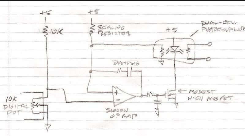
While I both sympathise and empathize, Steve, I am by nature a Feature Creep. There's also this pipe dream to turn this into a kind of kit to bring programmability to any amp.
The scaling resistor sets your end-to-end pot value. The controlling computer has to have a table of values to get you the taper you want out of the 256 available digipot values. The op-amp's frequency response has to be seriously degraded to just a few Hz or it's gonna oscillate something awful. It takes one of these to make a rheostat (variable resistor) or a pair to make a potentiometer (variable divider). And you still gotta match your own photocells and/or LEDs.
Good luck!Comment
-
Thanks for posting that!

It'll take me awhile to understand it, but it's a great start for me!!!Comment
Comment