Ad Widget

Collapse

Announcement

Collapse
No announcement yet.

On conjunctive filters

Collapse
X
 
  • Filter
  • Time
  • Show
Clear All
new posts

  • On conjunctive filters

    Just a little note on my latest learning experience at the scool of hard knocks.

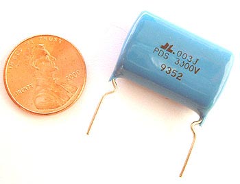
    I used a corrective/conjunctive filter in my last design, a 2 x el84 amp. By my figures with a 1500pf cap and 10k resistor I used a 600V rating for the cap (350 plate volts) and a 5 watt resistor. Well...It burned up. It didn't take any other parts with it, so thats good. But considering the voltage spikes at these higher frequencies these parts were clearly underrated. As evidenced by the fact that my capacitor is now a dead short and my resistor got so hot with that cap shorted that it melted the insulation on a nearby lead wire. With some research I read that these spikes can be two or three times the plate voltage. A regular 600V film cap failed horribly.

    So if you decide to use a conjunctive/ corrective filter, take the high ground and use generaously overrated parts and don't locate them near anything heat sensitive.

    My new parts are a 1KV mica "snubber" cap and a 10W cement resistor... I don't anticipate any more problems.

    Chuck
    "Take two placebos, works twice as well." Enzo

    "Now get off my lawn with your silicooties and boom-chucka speakers and computers masquerading as amplifiers" Justin Thomas

    "If you're not interested in opinions and the experience of others, why even start a thread?
    You can't just expect consent." Helmholtz

  • #2
    Hi Chuck

    Yes, the cap in a conjunctive filter will see peak voltages up to twice the B+. Maybe more if you're overdriving cr@p out of the power stage, and don't have those "flyback diodes" from plates to ground.

    The cap death suggests you are having a lot of spikes, so it would be an interesting experiment if you added those diodes and reported back to us whether they affect the tone, or blow out themselves. The 1kV mica cap might not blow, but what about your OT or tube sockets?

    I just repaired an old table radio where the conjunctive filter cap had gone short and smoked the resistor, too. In these radios they connect the filter network from plate to ground, so the cap has B+ across it just sitting there. I never got round to replacing it, but the radio seems to sound fine without it.
    "Enzo, I see that you replied parasitic oscillations. Is that a hypothesis? Or is that your amazing metal band I should check out?"

    Comment


    • #3
      Rather than connecting a conjunctive filter from plate to plate, it might be a better idea to connect use two of them- one each plate to the C.T. The peak voltage on each filter will be halved. The WEM dominator did it this way.

      Remember, if the resistor you use (in the single filter example) is equal to the plate to plate impedance of the OT, at a high frequency the filter can be dissipating as much power as the speaker is!

      Comment


      • #4
        Originally posted by Chuck H View Post

        My new parts are a 1KV mica "snubber" cap and a 10W cement resistor... I don't anticipate any more problems.

        Chuck
        Hi , Chuck , Dont use a mica cap !! as far as I know , they fail quick if the max voltage is reached , and can go leaky very easy ,(I see various over the years) use a plastic one MKT or MKP better , they have selfhealing propieties in the event of out of range usage.
        The flyback diodes another good idea too , they limit the HT spikes when you put the power amp really hard into overdrive , with lousy OTś they are the only way it can survive without frying.

        regards

        Comment


        • #5
          I got involved in a project where some significant current, 10 amps pk to pk, had to flow in a 166KHz resonant circuit. Most caps I stuck in there just melted. The Sprague 716P preformed without a single failure. They are actually rated for this kind of service. That's where I found out the 716P has copper leads and the 715P had copper plated steel leads. The 715P's would have worked but had slightly higher ESR.
          WARNING! Musical Instrument amplifiers contain lethal voltages and can retain them even when unplugged. Refer service to qualified personnel.
          REMEMBER: Everybody knows that smokin' ain't allowed in school !

          Comment


          • #6
            two of THESE in series will definitely hold!


            1500pF at 6kV! with 15kV surge!

            0.50 each at westfloridacomponents.com

            Comment


            • #7
              Thanks everyone for the replies.

              In no particular order...

              Tedmich, WOW those are truely tiny and cheap for such a cap. The epoxy dip could be misleading, I wonder if those are ceramic. The caps I bought are only 1kv but are designed for spikey voltage applications. So even though I spent alot more than I had to I should be alright.

              Steve, I don't think my sockets or tubes are in danger. The spike I used this filter to squash was not all that large on the scope. Of course, real world conditions must have changed something or the cap wouldn't have failed. I may try the diodes if it fails again or if I have some other related problem. And yes, this amp remains on 11 most of the time and pummels the innards out of the power tubes. And sounds great for it too

              Octal and Steve, Do you think using seperate R/C's from each primary to CT would be a better arrangement? Would this reduce the size of the voltage spikes because the cap already has all the B+ across it? I don't see how this filter could be dissapating as much wattage as the speaker. For one I would be getting 50 watts from a pair of EL84's and I'm pretty sure thats not possible. Also, the cap in the circuit seriously limits the current as there is no high current bottom end being passed...Isn't this right?

              Oskar, I'm not sure which caps your talking about. The ones I bought are designed for spikey high voltage applications. I they blow up I'll let you know so you can say 'I told you so'.

              Loudthud, is that 10 amps at 166khz!?! I can't imagine why all those caps failed . FWIW the cap I had in the circuit (that had all it's innards welded together) was a 600V 715P.

              Keep it comming. I'm may be learning something.

              Cheers

              Chuck
              "Take two placebos, works twice as well." Enzo

              "Now get off my lawn with your silicooties and boom-chucka speakers and computers masquerading as amplifiers" Justin Thomas

              "If you're not interested in opinions and the experience of others, why even start a thread?
              You can't just expect consent." Helmholtz

              Comment


              • #8
                IIRC it was two .047 @ 600V in series with a coil that was 8 turns of #12 house wire about 14 inches diameter. Now that I think of it, it was only 133KHz. The 800V and above parts have a slightly different internal construction. You have to derate the voltage at that frequency. Still it was about 250V pk-pk across each cap.
                WARNING! Musical Instrument amplifiers contain lethal voltages and can retain them even when unplugged. Refer service to qualified personnel.
                REMEMBER: Everybody knows that smokin' ain't allowed in school !

                Comment


                • #9
                  Originally posted by Chuck H View Post
                  I don't see how this filter could be dissapating as much wattage as the speaker. For one I would be getting 50 watts from a pair of EL84's and I'm pretty sure thats not possible. Also, the cap in the circuit seriously limits the current as there is no high current bottom end being passed...Isn't this right?

                  Chuck
                  he was saying power that the speaker is dissipating, not the max power the speaker can dissipate (so if you are putting out 15w of power, and 8 of those watts are at frequencies that the cap may pass, then 4w will pass through the cap and 4 through the transformer and then the speaker if the resistor value is equal to the P-P impedance.

                  Comment


                  • #10
                    I recieved my parts today. The amp is back together and sounding great. I'm in love again.

                    I hadn't realized but the original cap failing had been taking it's toll on the tone. I expect the cap was changing value a bit at a time. So that poor film cap had been crippled and had to heal itself repetedly. I thought for awhile that the amp had lost favor with my ears. But now with the correct values in and working properly it's golden. After about 30 min. with the amp cranked the resistor just got warm and no more intermittant scratch/pop sounds...Yet.

                    Chuck
                    "Take two placebos, works twice as well." Enzo

                    "Now get off my lawn with your silicooties and boom-chucka speakers and computers masquerading as amplifiers" Justin Thomas

                    "If you're not interested in opinions and the experience of others, why even start a thread?
                    You can't just expect consent." Helmholtz

                    Comment


                    • #11
                      AAaah. Got it. Even so, I measure 24 watts at the speaker with the amp at full tilt OD. So if this filter is soaking up half the power it's only at the pass frequency. And I would expect that because impedance is impedance and I have parallel loads in that sense. Actually I'm using 10k for the resistor and my OT is 8K. But close enough. I didn't figure the pass frequency for the cap but it should be pretty close to bacon frying. I don't suppose this amp could reproduce it's full wattage at that frequency and above.

                      Chuck
                      "Take two placebos, works twice as well." Enzo

                      "Now get off my lawn with your silicooties and boom-chucka speakers and computers masquerading as amplifiers" Justin Thomas

                      "If you're not interested in opinions and the experience of others, why even start a thread?
                      You can't just expect consent." Helmholtz

                      Comment


                      • #12
                        Originally posted by Chuck H View Post
                        AAaah. Got it. Even so, I measure 24 watts at the speaker with the amp at full tilt OD. So if this filter is soaking up half the power it's only at the pass frequency. And I would expect that because impedance is impedance and I have parallel loads in that sense. Actually I'm using 10k for the resistor and my OT is 8K. But close enough. I didn't figure the pass frequency for the cap but it should be pretty close to bacon frying. I don't suppose this amp could reproduce it's full wattage at that frequency and above.

                        Chuck
                        the amp could easily put out its max power above the pass frequency if the signal being fed into the amp is at or above the pass frequency. another thing is that an overdriven signal is mainly made up of harmonics.

                        so your A note is a 110hz, the second harmonic (220hz) is stronger than the fundamental (thats just how guitars work/sound) then the 3rd/330hz is less, 4th/440 is less and so on (lets just think of those right now, but past the 10th harmonic will sound. where the harmonics become insignificant depends on the instrument/pups and pup location). when you overdrive it, the 110 makes more of the harmonics already there. the 220hz makes 440hz, 660hz, 880hz ect. the 330 hz makes 660, 990, 1320 ect. the 440 makes 880, 1320, 1760, 2200 ect. the other harmonics probably dont create too much distortion. so suddenly your sound which has alot of 110, 220,330 and 440 and some of the rest suddenly has alot of harmonics higher up and not all that much of the 110 and 220hz. now imagine you are playing an A power chord with the amp cranked with all the harmonics.

                        also keep in mind when people rate amps they rate them at clean power. when you overdrive the amp there is the clean power + the harmonics on top of that.

                        depending on the f3 you may well be putting out alot of power through the resistor.

                        Comment


                        • #13
                          Well since I have no plans to overdrive this amp with a piccolo, harpsicord or banjo I think I'll be alright.

                          I'm sure I could be missing something but with 24 watts appearing at the speaker it seems impossible that there could be a dangerous amount of current in the filter since this pair of tubes can only put out 24 watts. Certainly more with spikey pulses but mow much? That isn't to say that certain conditions won't favor the filter over the OT. I just don't see it possible with this arrangement in real world guitar amp circumstances that the filter will ever be dissapating much.

                          If we're just kicking this around with semantics and exteremes I suppose my amp might fail horribly if someone wanted to amplify a 15khz 1VAC square wave at the input with the amp dimed for a half an hour. I don't anticipate that but maybe I should when I consider some of the looney things guitar players will do to their gear.

                          Chuck
                          "Take two placebos, works twice as well." Enzo

                          "Now get off my lawn with your silicooties and boom-chucka speakers and computers masquerading as amplifiers" Justin Thomas

                          "If you're not interested in opinions and the experience of others, why even start a thread?
                          You can't just expect consent." Helmholtz

                          Comment


                          • #14
                            was the f3 15khz? i couldnt see if you mentioned the f3, i may have missed it.
                            what may have happened is the cap scould have increased in value when it was being burnt up, letting lower frequencies through giving this problem. another thing to consider is that there may be some oscillations in the amp that the speaker cannot reproduce that were going through the cap/resistor. might want to have a look on an oscilloscope if you have any more issues.

                            Comment


                            • #15
                              Thanks. Yeh, I had the scope out constantly while designing and building this one. There WAS spikey business (I am pounding the piss out of these power tubes) but no oscillations. The filter and some tricky drive and bias control circuits using diodes have rendered the hard clipping nice and square. Of course this means that the filter has alot of work to do. I just didn't hire the right capacitor for the job. And yes, the old cap was moving up in value as it was failing. Or possibly acting more and more like a R/C. Which had me thinking my ears had stopped favoring this amp. FWIW I've been pounding on it ever since I put it back together. So far so good. In fact after thumping out power chords for a half hour I quickly flipped the standby switch and placed my finger on the new resistor. It was warm but I could easily hold my finger to it. I think (I hope) it's all good now.

                              Chuck
                              "Take two placebos, works twice as well." Enzo

                              "Now get off my lawn with your silicooties and boom-chucka speakers and computers masquerading as amplifiers" Justin Thomas

                              "If you're not interested in opinions and the experience of others, why even start a thread?
                              You can't just expect consent." Helmholtz

                              Comment

                              Working...
                              X