Ad Widget

Collapse

Announcement

Collapse
No announcement yet.

Tube FX loop design questions

Collapse
X
 
  • Filter
  • Time
  • Show
Clear All
new posts

  • Tube FX loop design questions

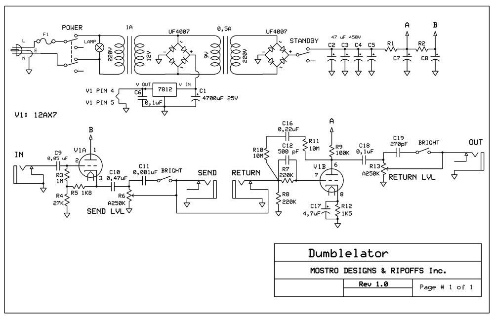
    Hi people, I recently finished my first tube amp, it has a passive FX loop, just a send and return jack between the last preamp gain stage and the phase inverter. As it is now it´s pretty useless, so I tried to make an external JFET-based active loop, but that never worked well (not enough headroom). So I decided to make a tube one, it´s the Dumblelator. I had to adapt it to what I can make, but since I don´t have that much experience with tubes, I have some questions for you.

    Here´s my schem:


    Questions:

    1) I´m gonna power the tube heaters with 12V DC.It should actually be 12.6V, but with a 7812 regulator I´ll get 12V. Is that OK, or will it be bad for the tube?

    2) Regarding supply voltages: Using xformers back to back like shown, I calculated that I´ll get, at the 2nd xformer primary (220V side) around 293V. After the rectifier bridge, I should get 293 x 1,414= 414,69V DC minus the diodes drop (all this is theory, haven´t tried it yet). Now, the part of the schem from the standby switch to the A and B points I´m not that sure... The point A is supposed to get 368V, and the point B 256V. I´m not that sure of how to get those values... I guess R1 and R2 could be 22K, and C7 / C8 could be 22uF? Also, are C2/3/4/5 too much filtering? could I do with just two 47 uF caps? That part of the schem is a gray area to me...

    3) About the fuse F1, I´m not that sure of the value. Would 1A slo blo be OK? Or less?

    4) anything else you see that wouldn´t work?

    Thanks for reading! Any help will be useful.

  • #2
    Tubes are not precision items. SOmething close to 12.6v is good enough. 12v for example. If you wanted to get anal about it, you could add a diode in series with the ground leg of the 7812. That would lift its ground reference a half volt or so, so its output would be that much higher also.


    A brief math note: when you use numbers like 293, 1.414 and who knows, maybe 317.568, your result can have no more significant digits than the term with the least. In other words, since 293 has the fewest significant digits (3 of them), then the answer can have no more than three as well. So while in arithmetic we could calculate long strings of digits, when you multiply 293 by 1.414, the answer is 414, not 414.69.


    You have not quite 2 watts of heater going on, and from that 400v B+, you might draw 5ma, that's another 2 watts. So the whole thing ought to draw maybe 5 watts tops, you think?

    5 watts from 220VAC is a miniscule current. Put some small value fuse in there to prevent fires if everything in there shorts. I don't like 1/4 amp fuses because they are a lot more expensive, and I find teeny fuses to be less mechanically robust.

    368 to 256 is a 112v drop. If you use 22k for R2, that means you are expecting 5ma through V1B. To my mind that seems high. But we can use it for discussion.

    414 to 368 is a 46v drop across R1. That is from the current for V1A plus the 5ma from V1B. Let us say V1A also draws 5ma. That is 10ma through R1. R=V/I, so 46v/.01A = 4600 ohms. I would try the standard value 4.7k as close enough.

    Now if you find tube currents are lower, you'd have to adjust those values. Once you have the circuit breadboarded and functioning, if the voltages are off, you can determine tube currents easily enough. Measure DC voltage across R4 and R12, and using the voltage you find plus the resistor value in each case, plug those into Ohm's Law and find the current. Once you know the tube currents you can adjust the B+ resistors as needed.

    That is at least a rough explanation.
    Education is what you're left with after you have forgotten what you have learned.

    Comment


    • #3
      Originally posted by Mostro View Post
      3) About the fuse F1, I´m not that sure of the value. Would 1A slo blo be OK? Or less?
      A Slo-Blo fuse is better (because of the filter cap surge when you switch on the amp)

      As for the fuse rating (txstrat confirmed this for me on another thread, although I knew I had read it somewhere before):

      Sum up the VA values and you get the whole VA of the secondaries. Divide that by the mains voltage and you get the primary amperage. Take the nearest value and multiply by two.
      Building a better world (one tube amp at a time)

      "I have never had to invoke a formula to fight oscillation in a guitar amp."- Enzo

      Comment


      • #4
        Boys, thanks for the answers. Very educational! I´ll keep your suggestions in mind. I´ll continue to refine the schem.

        Thanks!

        Comment


        • #5
          I get results with a 12au7 and the like with a circuit like this. If you use rack gear with an output level (like an EQ) you may not need the recovery stage.

          Comment


          • #6
            I would probably elevate the heaters 100-some volts. Check the tubes datasheet for the max heater to anode-voltage.

            Comment

            gebze escort kurtköy escort maltepe escort
            pendik escort
            betticket istanbulbahis zbahis
            deneme bonusu veren siteler deneme bonusu veren siteler
            casinolevant levant casino
            Working...
            X