Ad Widget

Collapse

Announcement

Collapse
No announcement yet.

Switching Noise

Collapse
X
 
  • Filter
  • Time
  • Show
Clear All
new posts

  • Switching Noise

    I've built quite a high gain amp and I'm getting a lot of hard, obnoxious buzz.

    Here is the output trace with no input signal applied - gain and volume on full.
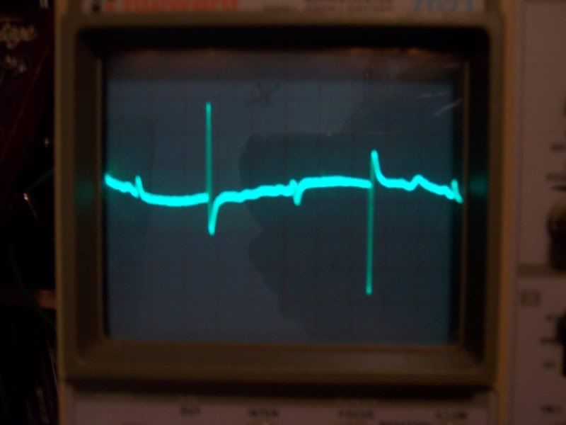


    I tried adding snubbers to the diodes (which are UF4007s in a full-wave bridge), which seemed to help a little bit, but not much. Here is the trace with 10nF snubbers across each diode and a 1uF cap across the HT secondaries (I think the latter is responsible for the "ringing" shape):
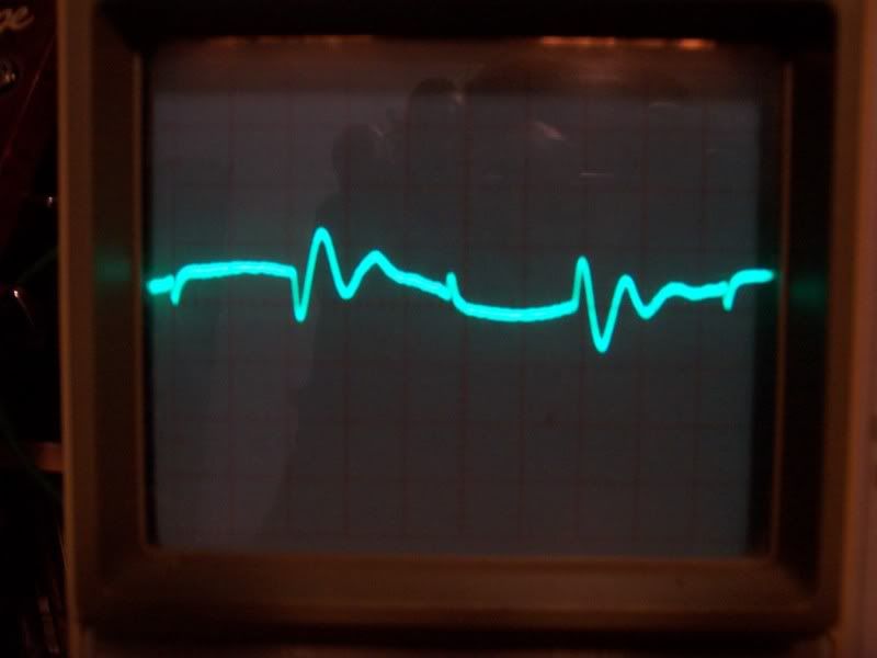


    Presumably what I am seeing is switching noise... and I can't seem to find much about the effectiveness of snubbers - is it actually possible to eliminate this noise? If so, what am I doing wrong with my 10nF caps?


    Also, my heater looks like this:
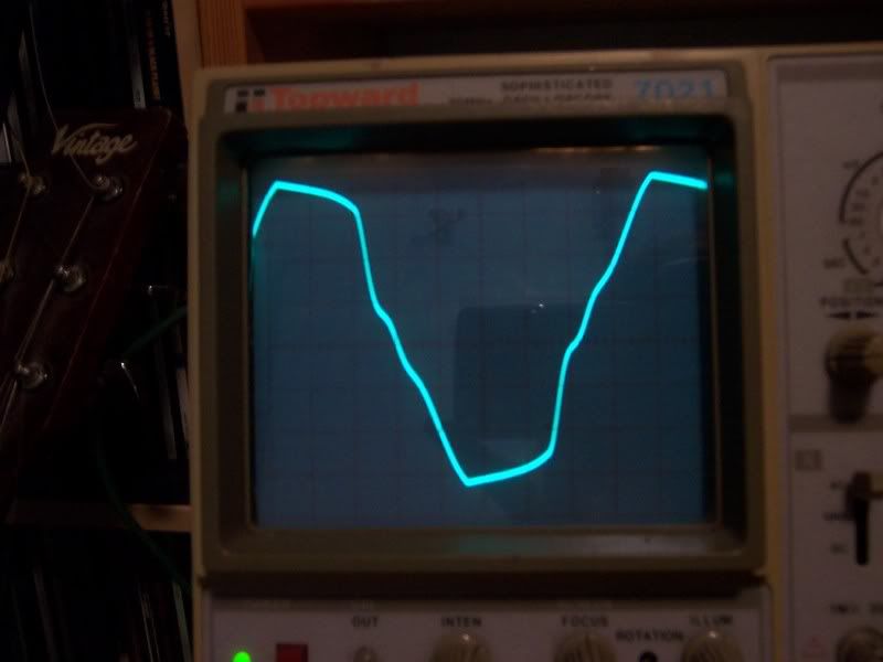


    how important is it that heaters are run off a pure sine wave?
    Last edited by harry; 10-19-2009, 01:02 AM.

  • #2
    Hi Harry,
    Why are you using UF4007s? They're an ultra fast ( hence the prefix "UF" ) version of 1N4007s, with a recovery time measured in nanoseconds, making them suitable for switching applications, so they're not really needed in "standard" applications like an "old fashioned" tube amp power supply is. I would advise you to use 1N4007s keeping the snubber caps in place and retest the rectifier's behavior with your o-scope.

    As to the o-scope traces, can you specify what the X-Y settings ( time-base and amplitude ) were for both of them? The first indeed looks like switching noise. As to the second ( heater supply ) trace, it's very strange to see such a "dirty" waveshape, since an AC heater's supply usually comes straight from the PT relevant winding so it should be a pure sine wave....can you specify what your heater's supply arrangement is like? ( PT ratings, wiring/lead dressing/wire twisting, presence of a real or virtual center tap to GND ( hum balance pot/resistors ) etc.

    Hope this helps

    Best regards

    Bob
    Last edited by Robert M. Martinelli; 10-19-2009, 01:33 AM.
    Hoc unum scio: me nihil scire.

    Comment


    • #3
      Thanks Bob, I'll see if I can get hold of some 1N4007s.


      The PT is a strange one.. it's from a Peavey Classic 30 which uses 4xEL84 and 3x12AX7.. I have it set up as follows:

      2.7ohm dropping resistor -> 6L6 -> 6L6 -> 3x12AX7 in parallel -> 3x12AX7 in parallel -> 2.7 ohm dropping resistor

      although I took the last 2.7 ohm out as despite my calculations, the heater voltage was a bit low. It's balanced well though - I now get 6.2-6.4v on each tube... but I'm clearly not as cunning as I thought I was, because I'm getting that horrible distorted wave.

      The way I calculated it, current requirements were identical - 750mA across 4xEL84s + 150mA across 3x12AX7s run in parallel in the PV; 900mA across everything in my design.

      Centre tap is going to cathode of cathode-biased power tube section through 2x100 ohm resistors. I tried just grounding it, didn't make any difference. Leaving it floating didn't do anything either.

      All wires are tightly twisted and I've tried to keep them orthagonal to signal wires/components as much as possible. When you turn down the master volume, it's silent. So the PI seems to be working just fine. It's just the first two triode gain stages and the subsequent DC cathode follower/stack that produce noise.

      my timebase is broken, but one period of a 550Hz sine wave fits into one division. the amplitude is 2V/div

      When I turn the power off, the spikes disappear instantly (and the high-frequency hum fades out)

      Comment


      • #4
        Originally posted by harry View Post
        The PT is a strange one.. it's from a Peavey Classic 30 which uses 4xEL84 and 3x12AX7.. I have it set up as follows:

        2.7ohm dropping resistor -> 6L6 -> 6L6 -> 3x12AX7 in parallel -> 3x12AX7 in parallel -> 2.7 ohm dropping resistor

        although I took the last 2.7 ohm out as despite my calculations, the heater voltage was a bit low. It's balanced well though - I now get 6.2-6.4v on each tube... but I'm clearly not as cunning as I thought I was, because I'm getting that horrible distorted wave.

        The way I calculated it, current requirements were identical - 750mA across 4xEL84s + 150mA across 3x12AX7s run in parallel in the PV; 900mA across everything in my design.

        Centre tap is going to cathode of cathode-biased power tube section through 2x100 ohm resistors. I tried just grounding it, didn't make any difference. Leaving it floating didn't do anything either.

        All wires are tightly twisted and I've tried to keep them orthagonal to signal wires/components as much as possible. When you turn down the master volume, it's silent. So the PI seems to be working just fine. It's just the first two triode gain stages and the subsequent DC cathode follower/stack that produce noise.

        my timebase is broken, but one period of a 550Hz sine wave fits into one division. the amplitude is 2V/div

        When I turn the power off, the spikes disappear instantly (and the high-frequency hum fades out)
        Hmmm....
        the original design used 4*0.76 A + 3*0.3 A=3.94 A ( 4 x EL84s in parallel draw 0.76 A each, 3 x 12AX7 in parallel draw 0.3 A each @6.3 V ), so the 0.9 A you figured out is not correct IMHO.

        Your "new" design uses 2*0.9 A + 6*0.3 A= 3.6 A, 0.34 A less than the original tube compliment, so no worries about the current requirements.

        As to the "center tap" arrangement, if your PT's heater winding does have a center tap, try just grounding it, you only need the two 100 Ohms resistors if the PT's heater winding doesn't have a center tap. Either with the center tap grounded, or with the artificial center tap, you should read some 3.15 VAC to GND on each heater winding leg ( balance="minimal hum" condition ). If you plan to use the two 100 Ohms resistors even if your PT's heater winding has a "real" center tap, then you need to leave the "real" CT disconnected. This is MANDATORY in case you want to use a "hum balance pot", failing to do so, by turning the pot too far away from its center position, you could either fry the pot due to excessive current, or burn the PT because with the pot turned fully CW or CCW, you would short one leg of the heater's winding to GND
        ( the other end of that leg being the grounded center tap ).

        Oh, I was forgetting.....on the first and second trace, apart from the switching noise, you also seem to have some residual ripple, so I'd check the +HT filter caps too....

        If throwing in 1N4007s doesn't eliminate the switching noise issue, you can raise the snubber caps' value to 22 nF ( 1000 V ).

        Hope this helps

        Best regards

        Bob
        Last edited by Robert M. Martinelli; 10-19-2009, 03:43 AM.
        Hoc unum scio: me nihil scire.

        Comment


        • #5
          Hi Bob,

          Sorry! I forgot to say: The power tubes on the classic 30 are run in series (with two dropping resistors); the filament winding is about 28 volts under load. In parallel with this is a DC rectified leg which feeds the 3x12AX7s. I can only imagine rectification produces around +37.8V, as they are wired in series. As they are running on 12.6v, the current requirements are halved.

          So in my amplifier, each "leg" as I described it is part of the chain in series.

          There are no centre taps on the transformer.

          I tried the 1N4007s; it did not make much difference... filtering is 150uF at first, then 4 stages of 47uF/10k filters/dropping... so it should be okay on paper.. it doesn't sound too bad at the moment (but probably because it's just hidden by the obnoxious buzz!).

          I will try upping the snubbers and take more photos.

          Thanks for your help Bob, it is much appreciated.

          Comment


          • #6
            I'm going to guess it's the old ground loop problem. The wire between bridge rectifier negative and first filter cap negative carries a high current that sounds like a hard, obnoxious buzz. This wire must not form any part of your ground system, or the buzzing noise will be coupled into your audio.

            So, you run one wire solely from rectifier negative to filter cap negative, and connect it to the rest of your ground system at filter cap negative, don't connect anything at the rectifier end.
            "Enzo, I see that you replied parasitic oscillations. Is that a hypothesis? Or is that your amazing metal band I should check out?"

            Comment


            • #7
              Hi Steve,

              I've pulled everything out and crocodile clipped it in to try connecting the wire at different points - still the same thing.

              At the moment I'm running 4x1n4007s with 33nF snubbing caps and a 10nF snubbing cap across the secondary. 100uF of filtering is connected direct to the OT, then goes through 10k to the rest of the power line. A ground goes from the capacitor - to a star point (connected also to this is the cathode resistor/capacitor and the signal ground coming from the preamp). This is then grounded to the chassis.

              Very confusing. More snubbing just turns the spikes to ringing.

              Comment


              • #8
                Well, I rectified the heaters and run everything on DC and it looks quiet on the scope (it's too late to turn the amp on and listen, but noise is a mere fraction of what it was).

                I guess there was a reason Peavey ran their preamp heaters off DC.

                Thanks for the advice.

                Comment


                • #9
                  Originally posted by harry View Post
                  More snubbing just turns the spikes to ringing.
                  If you're trying to snub turn off transients with capacitors only, you end up only lowering the frequency if the ring. To eat the transient energy, you need at least an R-C snubber to damp the ringing you get from caps and parasitic inductances.

                  Seems like there was a paper on the net about "calculating optimum snubbers" or something. Ah. Here it is: http://www.hagtech.com/pdf/snubber.pdf

                  You also need to do some serious thinking about how to keep the area of the active current loop small at the "blip" frequencies by twisting wires, using high frequency "shorting capacitors" etc.
                  Amazing!! Who would ever have guessed that someone who villified the evil rich people would begin happily accepting their millions in speaking fees!

                  Oh, wait! That sounds familiar, somehow.

                  Comment


                  • #10
                    Originally posted by harry View Post
                    Hi Bob,

                    Sorry! I forgot to say: The power tubes on the classic 30 are run in series (with two dropping resistors); the filament winding is about 28 volts under load. In parallel with this is a DC rectified leg which feeds the 3x12AX7s. I can only imagine rectification produces around +37.8V, as they are wired in series. As they are running on 12.6v, the current requirements are halved.

                    So in my amplifier, each "leg" as I described it is part of the chain in series.

                    There are no centre taps on the transformer.
                    Harry,
                    you don't need to apologize, it's my fault....I could have looked at the schematic first, instead of making assumptions....
                    Cheers
                    Bob
                    Hoc unum scio: me nihil scire.

                    Comment


                    • #11
                      Originally posted by R.G. View Post
                      Seems like there was a paper on the net about "calculating optimum snubbers" or something. Ah. Here it is: http://www.hagtech.com/pdf/snubber.pdf
                      Aha, I found this paper and tried to get my head around it but failed. Everything I tried didn't seem to eat up the transient.

                      Never mind, problem solved. Thanks for the advice R.G.

                      Comment

                      Working...
                      X