Announcement

Collapse
No announcement yet.

Fender AB763 Style Optocoupled Tremolo Circuit Question

Collapse
X
 
  • Filter
  • Time
  • Show
Clear All
new posts

  • Fender AB763 Style Optocoupled Tremolo Circuit Question

    Hey guys, I'm an amp builder that primarily deals with Marshall stuff. I've done a Fender AB763 circuit once, but don't have LOTS of experience with them.

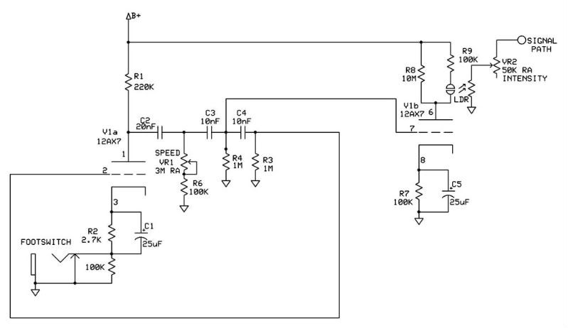
    I have a couple of questions regarding the LDR coupled tremolo circuit in the AB763 Twin Reverb amp.

    1) In regards to the 10M plate resistor in the lamp driver circuit that the LDR/100K resistor hooks up across, would it be OK to use another high value such as a 2.2M or a 3.3M, or would that bypass too much current and lower the voltage drop across it too low to fire the neon lamp?

    2) In regards to the speed & intensity pots in the oscillator circuit, what is the reason for the circuit calling for a reverse audio taper pot? Is it absolutely critical that these be a RA taper? How will the trem circuit respond if one were to use regular audio taper pots?

    3) Would it be OK to use a 250K pot in place of the normal 50K Intensity pot?

    Any input on this would be greatly appreciated.
    Last edited by Wilder Amplification; 11-15-2009, 01:13 AM.
    Jon Wilder
    Wilder Amplification

    Originally posted by m-fine
    I don't know about you, but I find it a LOT easier to change a capacitor than to actually learn how to play well
    Originally posted by JoeM
    I doubt if any of my favorite players even own a soldering iron.

  • #2
    1) I'm pretty sure the 10M just insures the Neon bulb will go off and leakage currents won't keep the neon lit. It's a function of the neon bulb's characteristics and how the drive tube is biased.

    2) The RA pot just gives an even sweep across the pot's rotation. Use a linear pot or hook an audio pot up backwards so that is '0' is max frequency, '10' is the slow frequency.

    3) Depending on the resistance range of the LDR, a 250K pot might only be usefull between 8 and 10.
    WARNING! Musical Instrument amplifiers contain lethal voltages and can retain them even when unplugged. Refer service to qualified personnel.
    REMEMBER: Everybody knows that smokin' ain't allowed in school !

    Comment


    • #3
      Originally posted by loudthud View Post
      1) I'm pretty sure the 10M just insures the Neon bulb will go off and leakage currents won't keep the neon lit. It's a function of the neon bulb's characteristics and how the drive tube is biased.

      2) The RA pot just gives an even sweep across the pot's rotation. Use a linear pot or hook an audio pot up backwards so that is '0' is max frequency, '10' is the slow frequency.

      3) Depending on the resistance range of the LDR, a 250K pot might only be usefull between 8 and 10.
      Thanks a bunch. The answer to question 3 brings to light another question -

      The LDR I have is one I bought from Antique Electronics Supply and I beileve it's the same one available from Mojo & Magic Parts. I use a Fluke 189 DMM that is rated to measure resistance up to 500M ohms. However, when trying to measure the "lamp off" resistance of the photoresistor, my meter will not read it. Does this indicate a problem with the internal photoresistor? Or is the "lamp off" resistance on these normally too high to measure?

      Also, in regards to question #1 from above, I understand your explanation of the purpose of that resistor in regards to the leakage currents. Does this mean that it would be OK to use a value such as 2.2M in place of the 10M resistor on the lamp driver?
      Jon Wilder
      Wilder Amplification

      Originally posted by m-fine
      I don't know about you, but I find it a LOT easier to change a capacitor than to actually learn how to play well
      Originally posted by JoeM
      I doubt if any of my favorite players even own a soldering iron.

      Comment


      • #4
        The LDR's resistance could certainly go over 500Meg. Your meter is just giving an over-range indication.

        Bruce of Mission Amps wrote recently about trying to find a combination of light and LDR to replace the Fender bugs. It's not as easy as you might think. IMHO the whole Fender circuit was designed around their Neon-CdS cell. Note the 100K cathode resistor. In it's day, the Neon bulb was a good alternative to an incandescent bulb. These days an LED probably provides the longest life but you need maybe 2-5mA to run one.

        It won't hurt anything to try 2.2Meg, it just may not sound exactly like a blackface Fender, good or bad. You may have to tweek on the 100K cathode resistor to compensate.
        WARNING! Musical Instrument amplifiers contain lethal voltages and can retain them even when unplugged. Refer service to qualified personnel.
        REMEMBER: Everybody knows that smokin' ain't allowed in school !

        Comment


        • #5
          Originally posted by loudthud View Post
          The LDR's resistance could certainly go over 500Meg. Your meter is just giving an over-range indication.

          Bruce of Mission Amps wrote recently about trying to find a combination of light and LDR to replace the Fender bugs. It's not as easy as you might think. IMHO the whole Fender circuit was designed around their Neon-CdS cell. Note the 100K cathode resistor. In it's day, the Neon bulb was a good alternative to an incandescent bulb. These days an LED probably provides the longest life but you need maybe 2-5mA to run one.

          It won't hurt anything to try 2.2Meg, it just may not sound exactly like a blackface Fender, good or bad. You may have to tweek on the 100K cathode resistor to compensate.
          Perfect...thanks a bunch! The thing I've always liked about Fender LDR coupled trems is the "sharp cutoff" characteristic provided by the "snap on snap off" function of the neon bulb (no in between brightness...it's either on or it's off).

          What I've got here in the shop is a Marshall Bluesbreaker Reissue that we gutted and upgraded the OT with a Radiospares RS DeLuxe clone OT from Mercury Magnetics, 7H choke from Mercury, and a point to point board with carbon comp resistors and Sozo Mustard Vintage caps. We also changed the stock 6L6s out for KT66s.

          Well, the customer and I have always liked the neon bulb LDR coupled Fender trem circuit due to the sharp cutoff it has unlike some others, so we thought it would be cool if we could ditch the Marshall tremolo and modify the original BB point to point layout slightly to accomodate the Fender LDR, and build the Fender AB763 trem circuit into this amp.

          However, I just realized that the speed & intensity pots in this reissue are not the same value as the Fender's LFO/Trem circuit. On top of that I'm having a hard time locating a 10M resistor at any of the local shops. I didn't wanna have to order it from Mojo but it's looking like I just might have to.

          One more question...upon testing the power supply tonight (tube sockets are not wired up yet) I also grounded the footswitch jack and was noticing that my bias voltage wants to drift less negative by about 2 volts when I do this (drifts from -56 to -54VDC). I'm using the standard 2.2M resistor right off of the diode in the bias supply (stock old school Marshall bias supply). Is it normal for this to occur even with such a high resistance to ground provided by the 2.2M? I wouldn't think that high of a resistance to ground would load the bias supply enough to do that, but since you seem to have more experience with Fender amps than I do maybe you can clarify this for me.

          If it's normal for it to do that I'll just have to remember to bias the amp with the footswitch grounded so that it will bias slightly on the cold side when the trem circuit is disengaged...or figure out how much it affects the bias current and remember to leave a bit of leeway. But would like to know if this is normal or if I may have an issue elsewhere.
          Last edited by Wilder Amplification; 11-15-2009, 06:13 AM.
          Jon Wilder
          Wilder Amplification

          Originally posted by m-fine
          I don't know about you, but I find it a LOT easier to change a capacitor than to actually learn how to play well
          Originally posted by JoeM
          I doubt if any of my favorite players even own a soldering iron.

          Comment


          • #6
            Are the pot and rest of the circuit hooked up? If all you have is the diode and cap, I can see where the cap would tend to charge up a little higher than normal by a volt or two.
            WARNING! Musical Instrument amplifiers contain lethal voltages and can retain them even when unplugged. Refer service to qualified personnel.
            REMEMBER: Everybody knows that smokin' ain't allowed in school !

            Comment


            • #7
              Originally posted by loudthud View Post
              Are the pot and rest of the circuit hooked up? If all you have is the diode and cap, I can see where the cap would tend to charge up a little higher than normal by a volt or two.
              Yes, the entire bias supply is hooked up and working.

              Another thing I noticed about this bias circuit is that for some reason it seems to take a couple of minutes to come down to its most negative value on power up. This power tranny doesn't have a separate bias tap so it's borrowed off of one side of the B+ secondary via a 150K ohm resistor between that one side of the B+ secondary and the diode, just like an old JTM-45. I know that 150K does some substantial current limiting but nonetheless I've personally never seen it take a couple minutes for the negative bias voltage to settle in like that.
              Last edited by Wilder Amplification; 11-15-2009, 04:48 PM.
              Jon Wilder
              Wilder Amplification

              Originally posted by m-fine
              I don't know about you, but I find it a LOT easier to change a capacitor than to actually learn how to play well
              Originally posted by JoeM
              I doubt if any of my favorite players even own a soldering iron.

              Comment


              • #8
                Well...I just had a "son of a bitch" moment.

                After looking at my schematic -


                I now realize what's going on in my circuit with the bias drift. The 150K and the 2.2M resistor form a voltage divider when the 2.2M resistor gets grounded by the footswitch. On Fenders they have a seperate 70 volt bias tap and because of this, they only have to use a 470 ohm before the 2.2M, which isn't a high enough value to cause that much of a voltage drop. But on this circuit it definitely would due to the high value of the 150K.

                Unfortunately, none of the Fenders featuring the LDR coupled trem circuit use a "borrowed" bias supply as all their PTs had the seperate 70 volt bias tap so now I'm wondering exactly how I'm gonna pull this off. Wondering if I should just let the trem tube oscillate at all times and just have the footswitch ground/unground the photoresistor/Intensity pot. The only concern with this would be if you'd still hear the familiar "ticking" sound as the lamp is triggered on/off.

                Another idea I had was placing a high value resistor in series with the 2.7K cathode resistor of the oscillator stage to reduce the gain of the oscillator enough to keep it from oscillating, then have the footswitch shunt that resistor when it closes...something like this -

                Last edited by Wilder Amplification; 11-15-2009, 05:32 PM.
                Jon Wilder
                Wilder Amplification

                Originally posted by m-fine
                I don't know about you, but I find it a LOT easier to change a capacitor than to actually learn how to play well
                Originally posted by JoeM
                I doubt if any of my favorite players even own a soldering iron.

                Comment


                • #9
                  OK so due to my issue explained above, I cannot use the negative cold bias method to bypass my optocoupled trem circuit due to the fact that this amp uses a "borrowed" bias supply from the HT winding and the resistor before the bias rectifier is too large to allow me to ground the 2.2M resistor without it pulling the bias voltage less negative by 2 volts. So I must use an alternate method to bypass this thing.

                  I had a couple of ideas...not sure if they'll work. Idea 1 was to have the footswitch ground/unground the Intensity pot/LDR while Idea 2 was to place a 220K ohm resistor between the cathode resistors/caps to ground and have the footswitch short/unshort this resistor.

                  My only concern with Idea 1 is that it would leave the trem valve oscillating and the neon bulb flashing, which may or may not introduce the all too familiar "ticking" sound, and with Idea 2, while it would keep the oscillator stage from oscillating by dropping the gain way down, the lamp driver may still be drawing enough current to keep the lamp lit up.

                  Would like to hear others' thoughts on this subject. Much appreciated.
                  Jon Wilder
                  Wilder Amplification

                  Originally posted by m-fine
                  I don't know about you, but I find it a LOT easier to change a capacitor than to actually learn how to play well
                  Originally posted by JoeM
                  I doubt if any of my favorite players even own a soldering iron.

                  Comment


                  • #10
                    The 10M resistor was added to help eliminate the ticking of the circuit without it.

                    You want to stop the oscillator? Put a switch under the speed pot, open to stop things. Or ground the grid.
                    Education is what you're left with after you have forgotten what you have learned.

                    Comment


                    • #11
                      OK the trem is working...sort of.

                      All components are brand new as this is a brand new build.

                      At 6Hz and above it oscillates fine. Below that, I can't get the oscillator to self start. Once I get the oscillator to start, it won't sustain oscillation below 6Hz very well unless I have a meter probe or an alligator clip jumper connected to the grid of the lamp driver with the other end of that not connected to anything. Right now with my meter connected to the oscillator circuit it's sustaining a 3.83Hz oscillation with the speed pot at the slow extreme with a 2VAC signal at the grid of the oscillator. However if I remove the meter probe it will not sustain oscillation at this low of a frequency.

                      Off the first cap in the feedback loop I measure 42VAC while at the 2nd feedback cap I measure about 10VAC.

                      Also, I seem to be picking up some sort of 60Hz hum at the roach that's only audible when the Intensity pot is at anything but zero. This hum increases in loudness as you turn the Intensity pot up.

                      B+ at the oscillator/lamp driver circuits is 415 running off of the screen filter cap. The voltages on the cathodes & plates very closely match the voltages shown on a Fender Deluxe Reverb amp AB763 schematic. Transformer is even the same as this amp at 330-0-330VAC with a GZ34 rectifier.

                      Any ideas? If it helps, I'm using Sozo Mustard Vintage coupling caps (typical .02/.01/.01 combo) as the phase shift caps in the oscillator circuit. Maybe these aren't the best type of cap to use in an oscillator feedback loop?
                      Last edited by Wilder Amplification; 11-26-2009, 07:08 AM.
                      Jon Wilder
                      Wilder Amplification

                      Originally posted by m-fine
                      I don't know about you, but I find it a LOT easier to change a capacitor than to actually learn how to play well
                      Originally posted by JoeM
                      I doubt if any of my favorite players even own a soldering iron.

                      Comment


                      • #12
                        When I first looked at your circuit I wondered why you took the LFO signal out at the middle of the phase shift string, but I said nothing because if it works it works. I know Fender did it that way also.

                        APparently it doesn;t work. ANd adding the antenna to the driver grid - and thus to the feedback loop - helps.

                        I wonder then could we not take the LFO signal off the plate of the LFO tube?

                        Disconnect the grid wire from R4 and monitor the LFO tube plate. Do we still have a problem starting or no? Implication being that the grid circuit might be loading down the oscillator.

                        My hypothesis would be to make the oscillator itself run reliably, then take a nice large cap from its plate to feed that grid. The grid will need a resistor to ground as well. In fact even in this circuit, I would have preferred the R4 connection run through a cap to pin 7 with an added grid return resistor at the grid. I don't like R4 being the grid return as well as part of an RC node. That is only my opinion.


                        Hum at the roach? Isolate the problem. Pull the tube. That kills the LFO and removes the amplification driving the neon lamp. Power the amp and turn up the intensity control. Is that hum still present? If so, turn out any flourescent lighting inthe room, the photocell could be picking it up. ANy difference?

                        DO we still have that cathode lift kill jack? IS the cutout contact 100%? In other words is the bottom end of C1/R2 zero ohms to ground?
                        Education is what you're left with after you have forgotten what you have learned.

                        Comment


                        • #13
                          Try increasing the cathode cap on the oscillator to 100uF.
                          WARNING! Musical Instrument amplifiers contain lethal voltages and can retain them even when unplugged. Refer service to qualified personnel.
                          REMEMBER: Everybody knows that smokin' ain't allowed in school !

                          Comment


                          • #14
                            Originally posted by Enzo View Post
                            When I first looked at your circuit I wondered why you took the LFO signal out at the middle of the phase shift string, but I said nothing because if it works it works. I know Fender did it that way also.

                            APparently it doesn;t work. ANd adding the antenna to the driver grid - and thus to the feedback loop - helps.

                            I wonder then could we not take the LFO signal off the plate of the LFO tube?

                            Disconnect the grid wire from R4 and monitor the LFO tube plate. Do we still have a problem starting or no? Implication being that the grid circuit might be loading down the oscillator.

                            My hypothesis would be to make the oscillator itself run reliably, then take a nice large cap from its plate to feed that grid. The grid will need a resistor to ground as well. In fact even in this circuit, I would have preferred the R4 connection run through a cap to pin 7 with an added grid return resistor at the grid. I don't like R4 being the grid return as well as part of an RC node. That is only my opinion.


                            Hum at the roach? Isolate the problem. Pull the tube. That kills the LFO and removes the amplification driving the neon lamp. Power the amp and turn up the intensity control. Is that hum still present? If so, turn out any flourescent lighting inthe room, the photocell could be picking it up. ANy difference?

                            DO we still have that cathode lift kill jack? IS the cutout contact 100%? In other words is the bottom end of C1/R2 zero ohms to ground?
                            @Enzo, yeah the cathode lift kill jack is in. Instead of using a 100K I used a 220K resistor there instead. The resistor on the jack kills the gain so that the LFO cannot oscillate. Also, the lamp driver shuts the neon bulb off as I measured the photocell's resistance with it switched off and it goes unmeasureable everytime it's switched off. Once the jack is grounded, it is actually like 0.3 - 0.4 ohms to ground.

                            I tried to ground the grid to stop the LFO/lamp driver but it made this god awful high pitched noise when I did that so I just stayed with the cathode lift jack.

                            @loudthud...I'll try increasing that bypass cap later today as per your suggestion.
                            Jon Wilder
                            Wilder Amplification

                            Originally posted by m-fine
                            I don't know about you, but I find it a LOT easier to change a capacitor than to actually learn how to play well
                            Originally posted by JoeM
                            I doubt if any of my favorite players even own a soldering iron.

                            Comment


                            • #15
                              LFO and lamp driver are two separate triodes. WHich grid did you ground? I was suggesting the LFO grid.

                              Just a thought, what happenes if you ground the bottom end of the LFO cathode resistor and cap right there instead of running over to the jack?
                              Education is what you're left with after you have forgotten what you have learned.

                              Comment

                              Working...
                              X