 Tweet
Tweet
No coincidence, it's the Real McKeen! :-)
In 2000 (so RG beat me to it I guess) I built a tube amp with a MOSFET regulator for the B+. The regulator was hooked up to the standby switch to provide soft start, and it also had current limiting, and a screen overcurrent detector that would latch the B+ off, requiring a cycle of the standby switch to bring it back.
I ended up ripping this feature out. Why? I didn't realize that guitar amps abuse their screen grids mercilessly, and the limiter would turn the amp off just as it was starting to sound good. The moral of the story is... well I don't know what it is to be honest! :-)
In hindsight I'd have only regulated the screen and preamp supply, or maybe I wouldn't have bothered. The amp is still working, however, regulator and all.
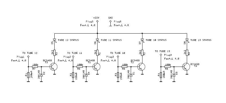
The original question seems a hard one to me. The only solution I can think of is to put the bias test resistors between cathodes and fuse, and accept the following:
1: They're going to get live if the fuse blows.
2: You're going to need two negative test jacks and four positive ones, because the negative ends of the test resistors aren't grounded. The voltage drop across the fuses would be significant.
In 2000 (so RG beat me to it I guess) I built a tube amp with a MOSFET regulator for the B+. The regulator was hooked up to the standby switch to provide soft start, and it also had current limiting, and a screen overcurrent detector that would latch the B+ off, requiring a cycle of the standby switch to bring it back.
I ended up ripping this feature out. Why? I didn't realize that guitar amps abuse their screen grids mercilessly, and the limiter would turn the amp off just as it was starting to sound good. The moral of the story is... well I don't know what it is to be honest! :-)
In hindsight I'd have only regulated the screen and preamp supply, or maybe I wouldn't have bothered. The amp is still working, however, regulator and all.
The original question seems a hard one to me. The only solution I can think of is to put the bias test resistors between cathodes and fuse, and accept the following:
1: They're going to get live if the fuse blows.
2: You're going to need two negative test jacks and four positive ones, because the negative ends of the test resistors aren't grounded. The voltage drop across the fuses would be significant.

Comment