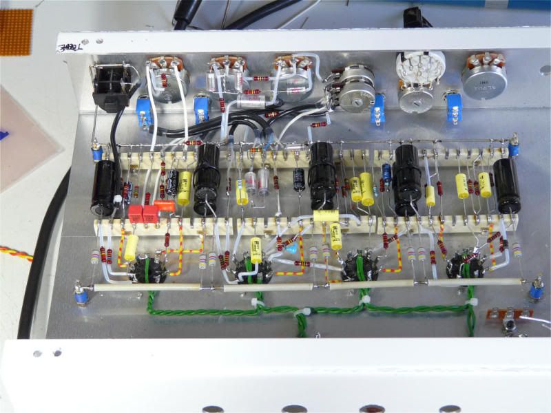
I've seen it done 3 different ways:
- Chassis mounted cap cans
- Filter caps on separate board
- Filters on main board
It seems though the filters on main board is not very common.
Is there something inherently bad about this layout I'm working on? (see attachment)
It has 2 8uF and 1 30uF caps right on the board, close to where they are needed. This also allows to ground them with the rest of their local circuits to diminish ground loops. I've also tried to leave more free space on each side for better "decoupling" with rest of circuit.
It seems to me that this should be better than running long wires to remotely located caps. But perhaps it really is a bad idea?
PS: If you,re wondering, the left is the cathode bias resistor and cap, the 100ohm ground reference resistors for the heater which are hooked on top of the cathode resistor for DC elevation, and the 4 screen resistors (power tubes are EL84)


Comment