Announcement

Collapse
No announcement yet.

The Official Dual Rail Thread

Collapse
X
 
  • Filter
  • Time
  • Show
Clear All
new posts

  • #61
    As long as Hammond, Edcor, Pacific, Heyboer, MCI, and a few other places are still in business I can't see giving my money to Mercury Mag. They've made a name for themselves but frankly it's just not worth the money. I've listened to many of their transformers and wondered why people still pay so much for them...I just don't get it. Maybe I would if I had a classic amp that I wanted to "keep original."

    On the other hand thanks for the tip- they probably have the stuff I need sitting on a shelf, ready to go!

    jamie

    Comment


    • #62
      Originally posted by imaradiostar View Post
      As long as Hammond, Edcor, Pacific, Heyboer, MCI, and a few other places are still in business I can't see giving my money to Mercury Mag. They've made a name for themselves but frankly it's just not worth the money. I've listened to many of their transformers and wondered why people still pay so much for them...I just don't get it. Maybe I would if I had a classic amp that I wanted to "keep original."

      On the other hand thanks for the tip- they probably have the stuff I need sitting on a shelf, ready to go!

      jamie
      Oh for Christ's sake...they're just end bells. They can't charge all THAT much for 'em.

      I'm not understanding your statement regarding "with a 5th and 6th rectifier you could get 350 on the 400VAC tap and 400 on the 470VAC tap". Call me stupid but could you clarify this for me?
      Jon Wilder
      Wilder Amplification

      Originally posted by m-fine
      I don't know about you, but I find it a LOT easier to change a capacitor than to actually learn how to play well
      Originally posted by JoeM
      I doubt if any of my favorite players even own a soldering iron.

      Comment


      • #63
        Originally posted by Wilder Amplification View Post
        Oh for Christ's sake...they're just end bells. They can't charge all THAT much for 'em.

        I'm not understanding your statement regarding "with a 5th and 6th rectifier you could get 350 on the 400VAC tap and 400 on the 470VAC tap". Call me stupid but could you clarify this for me?
        I don't think you're stupid- I think I may have described something that simply won't work.

        Somebody help me here- if the antek windings were arranged as FWCT then one of the two 400vac taps would be close to ground potential and one would be close to 470 volts, right?

        If the antek PT is wound the way I think it is it's designed to use with a bridge and a center tap- like a solid state amp. I don't think that it'll work the way I described- it would just blow diodes and make smoke that way.

        I was picturing it like some of the weber PT's- like a 700vct FWCT winding with a tap at 600 volts. I think I misunderstood!

        jamie

        Comment


        • #64
          Even if you can't use the 400 and 470 windings at the same time you can still run a choke and c input filter from one PT- you just need two extra diodes on the positive side of the supply, like bruce's drawing on the previous page but with a bridge instead of a FWCT rectifier arrangement.

          You'd get 470*1.4 minus some for around 650V for plates.

          You'd get 470*.9 minus some for around 420v for screens and preamps.

          I wouldn't be too surprised if it looked more like 640v/410v in the real world. Still very usable numbers, especially considering it's a 9 pound PT producing enough power for 4 kt88's and all it took was two extra diodes and a different connection of the choke that most amps would use anyway!

          It makes me want to build a hi-fi amp, even though I don't really need one. I have a pair of potted 14 pound 4k ultralinear outputs.

          jamie

          Comment


          • #65
            i thought about the choke imput for my build, but it seems that a choke input has a minimum current they operate on. the lower the current through the choke the higher the inductance has to be to work. when you are powering the screens there is a fair bit of a difference between full power and idle.
            i just did a quick example in PSU designer and a 5h choke. setting the transformer and choke resistance to 0.1ohm (negligible) and varied the current demands. 5ma had an output voltage of 420v, 20ma 370v, 40ma 330v, 60ma and above was stable at 300v.
            so an amp running 3 pair of 6550 would have 4ma per pair for the screens, and say 8ma for the preamp adding up to 20ma. with the 5ma choke you would have a voltage of 370v at idle, and 300v at full power (41Ma x3 +preamp =140ma+) and thats excluding any voltage drops from the choke or the power transformer's inherrant resistance. you could up the choke to around 15h to keep the voltage the same, but a choke of 15h that is rated to handle 150ma (i'd go 180-200ma to be safe) isnt going to be cheap, small or light. if your going to put a large piece of expensive iron on the amp you might as well put a second power transformer on. there is alot more selection which means you can shop around and get a good price.

            having said that, the compression would probably be pretty cool, but hard to be versatile

            Comment


            • #66
              Originally posted by imaradiostar View Post
              I don't think you're stupid- I think I may have described something that simply won't work.

              Somebody help me here- if the antek windings were arranged as FWCT then one of the two 400vac taps would be close to ground potential and one would be close to 470 volts, right?

              If the antek PT is wound the way I think it is it's designed to use with a bridge and a center tap- like a solid state amp. I don't think that it'll work the way I described- it would just blow diodes and make smoke that way.

              I was picturing it like some of the weber PT's- like a 700vct FWCT winding with a tap at 600 volts. I think I misunderstood!

              jamie
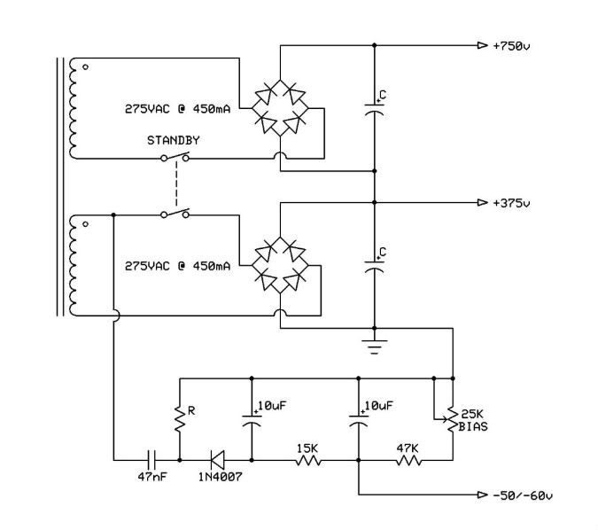
              Ah no that wouldn't work. In a solid state amp, that type of bridge arrangement is actually a "dual polarity" grounded center tap rectifier. While you COULD wire the two windings in series and the series node will become the CT, once you ground that CT you cannot ground the (-) side of the BR or you'll short the windings out on the negative cycle.

              You could do a stacked BR arrangement but you'd end up with about over 1200V B+.

              Now, Antec also makes their AN-3T275, which is a 300VA power tranny.

              http://www.antekinc.com/pdf/AN-3T275.pdf

              This one has two 275VAC windings, which you could do a stacked BR setup and end up with about 700-750 on the plates and about 350-375 on the screens, depending on what the tube idle load is. A circuit such as this would suffice -


              With that high of a plate voltage you'd also want about a 7.8K Zp-p load as well. In a stacked BR setup, both windings could supply up to 450mA, and current draw wouldn't exceed about 385, so you'd still be pretty stiff due to having reserve current.
              Last edited by Wilder Amplification; 04-14-2010, 12:36 PM.
              Jon Wilder
              Wilder Amplification

              Originally posted by m-fine
              I don't know about you, but I find it a LOT easier to change a capacitor than to actually learn how to play well
              Originally posted by JoeM
              I doubt if any of my favorite players even own a soldering iron.

              Comment


              • #67
                Originally posted by black_labb View Post
                having said that, the compression would probably be pretty cool, but hard to be versatile
                My real world experience shows the opposite- Duncan's PSU designer can't account for the parallel connection of both types of filter to one transformer. I've found that the sag of the screen supply is much less than the sag of the plate supply. Remember that in the real world chokes have a DC resistance greater than .1 ohms and the PT secondary is loaded (at least for a portion of each cycle) by charging the plate supply caps.

                Here are some real-world numbers from one of my in-process builds. PT is 800 VCT, diodes are 1n4007's, choke was a standard Fender unit with about 9Hy and 87 ohm DCR.

                "idle" B+ is 525v @ 176ma
                "idle" Vg2 is 347v @ 43ma

                "full power" B+ is 460v @ 760ma
                "full power" Vg2 is 325v @ 81ma

                I don't have numbers written down for higher Vg2 currents but I did try them and the drop wasn't as bad as you would expect. I also don't plan to load this PT down with 760ma- it was a "worst case" test. The hardest I'd load it would be around 450ma which gives between 490 and 495 volts DC. The choke supply can be loaded pretty heavily and still doesn't drop as severely as the plate supply.

                If for some reason the choke supply is floating too high you can always clamp it with zeners while idling and the screens will take what they need- wasting 40 or 50 ma in a stack of zeners still seems like a fair tradeoff for longer tube life, higher output efficiency and a better regulated screen supply.

                Jon- have you built the stacked arrangement with the 3T275 antek? I built that arrangement with a 1T200 for a pair of 6L6's at low power but haven't had a chance to get a bigger PT. I think it'd be a good solution to try.

                Thanks for catching my mistake- I should have been studying and not thinking about amps!

                Comment


                • #68
                  Originally posted by imaradiostar View Post
                  Jon- have you built the stacked arrangement with the 3T275 antek? I built that arrangement with a 1T200 for a pair of 6L6's at low power but haven't had a chance to get a bigger PT. I think it'd be a good solution to try.

                  Thanks for catching my mistake- I should have been studying and not thinking about amps!
                  I have not. I only just discovered it while I was lookin' through their other transformers and that was the closest thing to one with dual 225VAC windings (which I wish they'd make one with exactly those voltages).

                  The fact that it's a 300VA gives it a bit of reserve current for minimal sag. Would be good for a hi-fi amp...or a super heavy metal amp that stays tight all the way up to the top with no bottom sag.
                  Jon Wilder
                  Wilder Amplification

                  Originally posted by m-fine
                  I don't know about you, but I find it a LOT easier to change a capacitor than to actually learn how to play well
                  Originally posted by JoeM
                  I doubt if any of my favorite players even own a soldering iron.

                  Comment


                  • #69
                    Originally posted by imaradiostar View Post
                    My real world experience shows the opposite- Duncan's PSU designer can't account for the parallel connection of both types of filter to one transformer. I've found that the sag of the screen supply is much less than the sag of the plate supply. Remember that in the real world chokes have a DC resistance greater than .1 ohms and the PT secondary is loaded (at least for a portion of each cycle) by charging the plate supply caps.

                    Here are some real-world numbers from one of my in-process builds. PT is 800 VCT, diodes are 1n4007's, choke was a standard Fender unit with about 9Hy and 87 ohm DCR.

                    "idle" B+ is 525v @ 176ma
                    "idle" Vg2 is 347v @ 43ma

                    "full power" B+ is 460v @ 760ma
                    "full power" Vg2 is 325v @ 81ma

                    I don't have numbers written down for higher Vg2 currents but I did try them and the drop wasn't as bad as you would expect. I also don't plan to load this PT down with 760ma- it was a "worst case" test. The hardest I'd load it would be around 450ma which gives between 490 and 495 volts DC. The choke supply can be loaded pretty heavily and still doesn't drop as severely as the plate supply.

                    If for some reason the choke supply is floating too high you can always clamp it with zeners while idling and the screens will take what they need- was
                    ting 40 or 50 ma in a stack of zeners still seems like a fair tradeoff for longer tube life, higher output efficiency and a better regulated screen supply.
                    thats interesting. the mechanism i was trying to isolate was the choke not acting as a choke input filter at low currents/low inductance where the current is not substancial enough to "charge up" the choke. when there was enough current flowing through a choke it would act as a choke input filter and drop the voltage to the 0.9xVAC expected.

                    i am not sure how accurate psu is and wether it takes everything into account. i had heard about the phenomenon somewhere and tested it in psu which supported what someone mentioned. there's also the fact that chokes will have higher inductance below their rated current. i dont know how much the inductance changes though.

                    Comment


                    • #70
                      Originally posted by black_labb View Post
                      thats interesting. the mechanism i was trying to isolate was the choke not acting as a choke input filter at low currents/low inductance where the current is not substancial enough to "charge up" the choke. when there was enough current flowing through a choke it would act as a choke input filter and drop the voltage to the 0.9xVAC expected.
                      A choke input filter has a "critical current". Above the critical current the output is 0.9 x VAC, below it, it jumps up to 1.4 x VAC. It's caused by the choke current becoming discontinuous, and you can find the equation for it with a quick google, if PSU Designer doesn't do it.

                      The higher the inductance of the choke, the lower the critical current. A swinging choke is one that's deliberately allowed to saturate heavily, so it has a high inductance for low currents and a low inductance for high currents. This allows a choke input filter to be made with a smaller, cheaper choke, less copper and bleeder losses, and better transient response.

                      As I hinted by mentioning bleeder losses, if you can't tolerate the jump in voltage, you need to install a bleeder resistor to keep the load current always above the critical value.

                      RDH4 has a design procedure for all of this...
                      "Enzo, I see that you replied parasitic oscillations. Is that a hypothesis? Or is that your amazing metal band I should check out?"

                      Comment


                      • #71
                        Something else that came to mind...on a dual rail setup, since the screens are ran at 1/2 the plate voltage are screen resistors even needed? Or is it still a good idea to use some sort of low value resistor on each screen so that the screens are somewhat isolated from each other?
                        Jon Wilder
                        Wilder Amplification

                        Originally posted by m-fine
                        I don't know about you, but I find it a LOT easier to change a capacitor than to actually learn how to play well
                        Originally posted by JoeM
                        I doubt if any of my favorite players even own a soldering iron.

                        Comment


                        • #72
                          Originally posted by Wilder Amplification View Post
                          Something else that came to mind...on a dual rail setup, since the screens are ran at 1/2 the plate voltage are screen resistors even needed?
                          That depends entirely upon the load impedance. If the load line passes below the knee of the curves, you need screen stoppers. (And the chances are it will pass below the knee, 'cause that's where guitar amps sound best!)

                          Comment


                          • #73
                            Originally posted by Merlinb View Post
                            That depends entirely upon the load impedance. If the load line passes below the knee of the curves, you need screen stoppers. (And the chances are it will pass below the knee, 'cause that's where guitar amps sound best!)
                            Actually believe it or not, it crosses right at the knee. Here's a composite load line plot of the amp with a 600V B+, a 300V Vg2 supply and a 5K Zp-p.

                            Jon Wilder
                            Wilder Amplification

                            Originally posted by m-fine
                            I don't know about you, but I find it a LOT easier to change a capacitor than to actually learn how to play well
                            Originally posted by JoeM
                            I doubt if any of my favorite players even own a soldering iron.

                            Comment


                            • #74
                              Originally posted by Wilder Amplification View Post
                              Actually believe it or not, it crosses right at the knee. Here's a composite load line plot of the amp with a 600V B+ and a 300V Vg2 supply.
                              It's pretty close though, and since the speaker impedance increases at resonance, I would certainly advise stoppers in this instance. KT88s will die if you give them the chance!
                              (I bet it turns out that you like it better with a 16 ohm speaker on the 8 ohm tap )

                              Comment


                              • #75
                                Originally posted by Merlinb View Post
                                It's pretty close though, and since the speaker impedance increases at resonance, I would certainly advise stoppers in this instance. KT88s will die if you give them the chance!
                                (I bet it turns out that you like it better with a 16 ohm speaker on the 8 ohm tap )
                                And this is EXACTLY why I never got into the engineering and mathematical side of this shit for the longest time...because you can't calculate tone!!! lol

                                Still though...I find the load lines a very useful tool for getting a visual representation of how all of the engineering and mathematical data works and comes together, which is why I even got into it as of recently in the first place. It explains a lot of things that I just took for granted coming from someone else or tried for myself and never bothered to see how it all worked. Now that I've learned how to calculate and plot all the electrical parameters all out it's very easy to see the how and the why behind why you can do certain things and why it's not a good idea to do others...which makes this a "not so blind" art.

                                I'll have to try it with a 1 step up mismatch...the whole thing looks very good on paper, but as we all know, in the end it's all about how it all sounds, not how it looks on paper.
                                Jon Wilder
                                Wilder Amplification

                                Originally posted by m-fine
                                I don't know about you, but I find it a LOT easier to change a capacitor than to actually learn how to play well
                                Originally posted by JoeM
                                I doubt if any of my favorite players even own a soldering iron.

                                Comment

                                Working...
                                X