Originally posted by mooreamps
View Post
Ad Widget
Collapse
Announcement
Collapse
No announcement yet.
imbalanced 12ax7's due to 12.6v filament
Collapse
X
-
I think what he means by the stages being paralleled is that the grids are joined together. Both stages have their own separate plate/cathode resistors and separate coupling caps. One stage is LED biased while the other stage is biased via the 1.5K resistor.Jon Wilder
Wilder Amplification
Originally posted by m-fineI don't know about you, but I find it a LOT easier to change a capacitor than to actually learn how to play wellOriginally posted by JoeMI doubt if any of my favorite players even own a soldering iron.
-
My eyes are not as good as they once were, but I don;t recall seeing where you tried a different 12AX7 in the socket. You mentioned "new tubes," but I got the impression those were your power tubes.
You can;t ground your meter and measure those grid voltages or indeed you get seemingly way over the top bias. But you can measure the voltage between grid and cathode with your meter. Your grounded meter won;t load down the cathode voltage reading, so you can believe that. Then take the grid-cathode reading, and calculate grid voltage based upon that cathode voltage. it will me MUCH closer to the truth.
It surely has nothing to do with the heater voltage.Education is what you're left with after you have forgotten what you have learned.
Comment
-
i should really scan up a schematic, will try to do soon.
the grid leak resistors on the PI both measure 330k as expected.
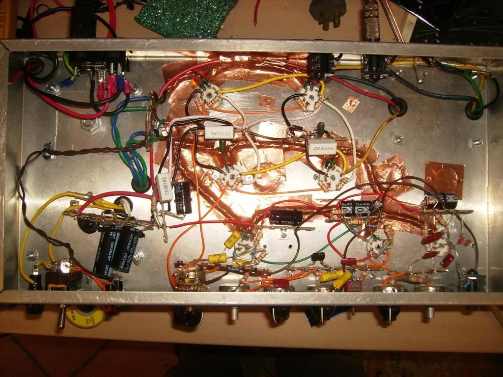
i've also checked the grid leak resistors on the power tubes (1m dual gang lin pot with a 220k resistor from the grid/wiper to ground, to aproximate a log pot and having a fixed resistor from the grids to ground incase the wiper goes) as expected the resistance to ground from the plates of the PI tubes is 180k with the control on full and increases to 1m when on min. the resistance from the grids/wiper to ground is 180k at max and reduces to nothing at 0.
for the input there are 2 parallel triodes from one 12ax7. the grids are directly connected so what shows on one grid should be on the other. will check that there isnt a cold solder joint blocking leaked dc there but both sides sound right.
will double check everything as these values arent making sense.
Comment
-
and he has a plate coupling cap between both gain stages ?
-g
Comment
-
Re-read the original post if you could and all should become clear -Originally posted by mooreamps View Postand he has a plate coupling cap between both gain stages ?
-g
This implies that he's doing something similar to a Lead/Super Lead input stage with the grids tied together I do believe so NATURALLY there'd be two separate output coupling caps.Originally posted by black_labb*in my earlier tests i noticed that the plate voltage on the 12ax7 on the input triodes were very different. the input has 2 triodes in parrallel with different cathode bias systems and a different coupling cap out (one is designed to be a bright style channel while the other is for a normal channel). one uses a red led for biasing and the other uses a 1k5 resistor (with a .82uf cap bypassing it). the one with the 1k5+cap has a plate voltage around 95v, while the other is around 150v. both are running from a power supply node with a voltage of ~210v. this did not correct itself with a tube change.Last edited by Wilder Amplification; 04-09-2010, 09:01 AM.Jon Wilder
Wilder Amplification
Originally posted by m-fineI don't know about you, but I find it a LOT easier to change a capacitor than to actually learn how to play wellOriginally posted by JoeMI doubt if any of my favorite players even own a soldering iron.
Comment
-
just a useless update
measured resistances with a multimeter and all resistances were normal. i am still bewildered as to why i am getting very mismatched readings. havent tried the changing of the heaters, but it doesnt make sense to be the problem. just is the only common thing aside from both being 12ax7's.
Comment
-
yes i have. thank you very muchOriginally posted by Wakculloch View PostHave you left off the ac ground reference cap on the second PI triode?
i didnt realise that there needed to be an ac ground reference there. guess i've gotten by without knowing that as i've been using -ve feedback on my other designs where there is a ltp.
still need to figure out the odd input triode voltages, but thats not as crucial.
Comment


Comment