Ad Widget

Collapse

Announcement

Collapse
No announcement yet.

What is this presence control actually doing? Should I tie the nfb loop in elsewhere?

Collapse
X
 
  • Filter
  • Time
  • Show
Clear All
new posts

  • What is this presence control actually doing? Should I tie the nfb loop in elsewhere?

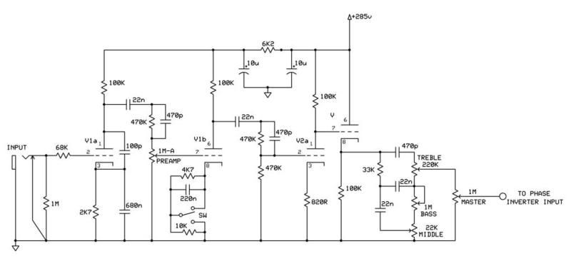
    So I wired up an amp with the following schematic:
    http://home.westman.wave.ca/~vwtweak...uly10%20jp.jpg

    I took the presence control from an old 5f6a schematic I found (I used a bigger pot though). The nfb is wired into the tone stack rather than one of the previous preamp stages, which I haven't seen done very often, but I didn't have a stage in the preamp after the tonestack but before the PI so it seemed like the place to tie it into.

    It definitely affects the sound, but almost seems like an extension of the mid control.. Seems to act like a scoop control, or something like that, not really like I expected a presence control to act.
    I'm not saying I mind what it does, it's an interesting control to have on the amp, but I would probably prefer having a more traditional control over presence.

    What is this control actually doing? (sorry the theory behind this type of thing is not one of my strong points).
    And secondly, is there a better location that I could tie this into?

    I appreciate any help on the matter.
    Thanks.

  • #2
    What the presence control typically does is shelve high frequencies out of the NFB loop. With less high frequencies in the NFB loop, less highs get cancelled at the amp's output and you end up with a perceived boost in the high frequencies.

    The way they did this here does in fact look like it lifts the mid control from ground.

    You could probably tie it in at V2a's cathode, BUT you'll more than likely have to reverse the OT primary wires at the output tube plates to reverse the phase of the OT secondary's output signal so that it is out of phase with the signal at V2a's cathode.
    Jon Wilder
    Wilder Amplification

    Originally posted by m-fine
    I don't know about you, but I find it a LOT easier to change a capacitor than to actually learn how to play well
    Originally posted by JoeM
    I doubt if any of my favorite players even own a soldering iron.

    Comment


    • #3
      Interesting.. And the reason for reversing the phase of the OT secondaries is because each stage in the preamp (the way they're configured in this case) is an inverting gain stage.. ?

      In any case, the way I've done it isn't exactly doing the same thing as the presence control typically does then.. right? Would there be a more appropriate term for what I'm doing with this control? I'm just thinking from a labelling perspective.

      Originally posted by Wilder Amplification View Post
      What the presence control typically does is shelve high frequencies out of the NFB loop. With less high frequencies in the NFB loop, less highs get cancelled at the amp's output and you end up with a perceived boost in the high frequencies.

      The way they did this here does in fact look like it lifts the mid control from ground.

      You could probably tie it in at V2a's cathode, BUT you'll more than likely have to reverse the OT primary wires at the output tube plates to reverse the phase of the OT secondary's output signal so that it is out of phase with the signal at V2a's cathode.

      Comment


      • #4
        Regarding your OT phasing question, you are correct. If you connect it to V2a's cathode and don't reverse the OT leads it will become a positive feedback loop and turn into the "screaming banshee of death".

        Regarding your preseonce control operation question...no because it's affecting the tone stack response as well. Not sure on what to label it as I haven't heard what it does...just think of any tonally descriptive term and name it that lol.

        BTW...I made a couple of improvements to your preamp circuit. Take note of the extra Pi filter in the power supply as well as the improved shunt switching in your V1b cathode circuit -


        Much better to switch the cathode circuit this way as the DC path is never broken.

        I also dropped the value of V2b's cathode bypass cap as the original 10uF would pretty much boost gain for everything within the audio pass band whereas the lower value there would help to tighten the low end up some by helping to shelve bass somewhat and work against possible low end distortion. If it shelves too much for your liking experiment with a 330nF or a 470nF as well, but I wouldn't go any lower than that. You can also experiment with lower value coupling caps between the first two stages to tighten it up even more if you wish as well as maybe try a 150K or a 220K on the first stage plate resistor. If the highs get too fizzy you can always throw a 470pF or a 1nF bypass cap across stage 2's plate resistor as well as remove the two 470pF treble peakers that are in their stock. Experimentation is key...season to taste. Lotsa room to play around with a 2203/2204 circuit.
        Last edited by Wilder Amplification; 07-07-2010, 07:32 AM.
        Jon Wilder
        Wilder Amplification

        Originally posted by m-fine
        I don't know about you, but I find it a LOT easier to change a capacitor than to actually learn how to play well
        Originally posted by JoeM
        I doubt if any of my favorite players even own a soldering iron.

        Comment


        • #5
          Cool! Thanks for the advice.

          I'm definitely going to implement your improved switching in the v1b cathode circuit.

          As for the increased filtering with the Pi filter, are you talking about adding 2 extra 10uf caps? Like I inserted here?
          http://home.westman.wave.ca/~vwtweak...uly10%20jp.JPG

          Or utilizing the one that I already have and adding one more for the Pi filter.

          I don't seem to have much issue with noise or anything like that. Why do you suggest the extra filtering?

          And increasing the 1st plate resistor lowering the V seen at the plate.. This would be to decrease headroom further?
          Last edited by thehoj; 07-07-2010, 02:09 PM.

          Comment


          • #6
            Originally posted by thehoj View Post

            As for the increased filtering with the Pi filter, are you talking about adding 2 extra 10uf caps? Like I inserted here?
            http://home.westman.wave.ca/~vwtweak...uly10%20jp.JPG

            Or utilizing the one that I already have and adding one more for the Pi filter.

            I don't seem to have much issue with noise or anything like that. Why do you suggest the extra filtering?
            Utilizing the last one you already have and adding one more pi filter after it. The reason for it is so that you only have two out of phase stages on each filter cap. By separating stages so that you're only running 2 out of phase stages from one filter cap, this ensures that one stage isn't drawing current from the same filter cap at the same time, which reduces intermodulation distortion between stages.

            If you look at a Marshall 2203/2204 schematic you will see that they use a dual can filter cap with one side of it feeding V1's stages while the other side feeds V2's stages with a 10K resistor between the two caps in the can.

            Originally posted by thehoj
            And increasing the 1st plate resistor lowering the V seen at the plate.. This would be to decrease headroom further?
            No...it would actually INCREASE the headroom. The difference between your static "zero signal" plate voltage and your B+ supply voltage at the B+ end of the plate resistor sets how high the plate voltage can swing up to with input signal (maximum possible signal swing = B+ supply voltage when the tube is pushed into cutoff). Using a bigger resistor will drop the voltage at the plate end yes, but this INCREASES the voltage differential across the resistor (i.e. between zero signal plate and B+ voltage...i.e. pulls the static plate voltage further away from the voltage at the B+ source end of the plate resistor), which increases the available "swing" of that stage.
            Jon Wilder
            Wilder Amplification

            Originally posted by m-fine
            I don't know about you, but I find it a LOT easier to change a capacitor than to actually learn how to play well
            Originally posted by JoeM
            I doubt if any of my favorite players even own a soldering iron.

            Comment


            • #7
              Originally posted by Wilder Amplification View Post
              Utilizing the last one you already have and adding one more pi filter after it. The reason for it is so that you only have two out of phase stages on each filter cap. By separating stages so that you're only running 2 out of phase stages from one filter cap, this ensures that one stage isn't drawing current from the same filter cap at the same time, which reduces intermodulation distortion between stages.

              If you look at a Marshall 2203/2204 schematic you will see that they use a dual can filter cap with one side of it feeding V1's stages while the other side feeds V2's stages with a 10K resistor between the two caps in the can.
              Interesting. I will definitely do that, I have a couple extra 10uf 450v caps.

              Originally posted by Wilder Amplification View Post
              No...it would actually INCREASE the headroom. The difference between your static "zero signal" plate voltage and your B+ supply voltage at the B+ end of the plate resistor sets how high the plate voltage can swing up to with input signal (maximum possible signal swing = B+ supply voltage when the tube is pushed into cutoff). Using a bigger resistor will drop the voltage at the plate end yes, but this INCREASES the voltage differential across the resistor (i.e. between zero signal plate and B+ voltage...i.e. pulls the static plate voltage further away from the voltage at the B+ source end of the plate resistor), which increases the available "swing" of that stage.
              Wow, somehow I never really understood that.. In my head it was always like "higher voltage at the plate is more headroom".
              I've been reading the merlin triode gain stage documentation recently, and so this is actually making sense to me. I'll be playing around with this a bit tonight.. Hopefully I can try some of it without messing up my layout too much.

              Comment


              • #8
                Higher B+ at the B+ source (i.e. the side of the plate resistor that is connected to the power supply) will give more headroom yes. But a higher voltage differential between the plate voltage and the B+ voltage source under "zero signal conditions" (i.e. a bigger voltage drop across the plate resistor at idle) will give you more headroom on the positive swing of the output signal at the exchange for headroom on the negative swing.

                Think of your idle plate voltage as your "zero" (since the coupling cap blocks the DC plate voltage, it is in fact your "zero" under zero signal conditions). The farther away your "zero" is from the B+ source voltage the higher the positive swing can swing. If the plate voltage = 1/2 your B+, you will have enough headroom for a 100% symmetrical output signal as your output signal will be able to swing equally in both direction between ground and B+.
                Last edited by Wilder Amplification; 07-08-2010, 02:15 AM.
                Jon Wilder
                Wilder Amplification

                Originally posted by m-fine
                I don't know about you, but I find it a LOT easier to change a capacitor than to actually learn how to play well
                Originally posted by JoeM
                I doubt if any of my favorite players even own a soldering iron.

                Comment


                • #9
                  Originally posted by Wilder Amplification View Post
                  Utilizing the last one you already have and adding one more pi filter after it. The reason for it is so that you only have two out of phase stages on each filter cap. By separating stages so that you're only running 2 out of phase stages from one filter cap, this ensures that one stage isn't drawing current from the same filter cap at the same time, which reduces intermodulation distortion between stages.

                  If you look at a Marshall 2203/2204 schematic you will see that they use a dual can filter cap with one side of it feeding V1's stages while the other side feeds V2's stages with a 10K resistor between the two caps in the can.
                  What's your take on that last 10uf cap and then the 2 other 10uf caps in the pi filter all sharing a ground?..

                  Comment


                  • #10
                    Actually in your schematic you already have a 10uF that the whole preamp is pulling from. You just need to add one more so that V1 can be taken off of the one you already have and it can have its own. I just included the pre-existing 10uF in my schematic and added the decoupling resistor along with the 2nd filter cap on V1.

                    In regards to grounding them together...if you're gonna do that then the preamp needs to be grounded to that exact same point. When I do amps with dual can caps I tie all of the preamp stage grounds together, then take one wire from that point straight to the common negative of the filter cap can, then ground it to the chassis at that point. Works like a charm.
                    Jon Wilder
                    Wilder Amplification

                    Originally posted by m-fine
                    I don't know about you, but I find it a LOT easier to change a capacitor than to actually learn how to play well
                    Originally posted by JoeM
                    I doubt if any of my favorite players even own a soldering iron.

                    Comment


                    • #11
                      Cool. Okay, I ended up just adding that one 10uf cap with the decoupling resistor, and did use seperate grounds, as it didn't turn out to be too much extra work. Seems to be working good.
                      I also decided that I like a 10k resistor for the cathode on v1b with a .2uf bypass cap and didn't need to switch between a 5kohm resistor. So I'm using that switch now as a bright switch, switching in and out a 500pf cap on the volume control.

                      I think I'm gonna call what I had originally thought of as presence as a scoop control now.. It seems to scoop the mids out as I turn it up. That's what'll make sense to me.

                      Anyways, here's where I'm at with it now. Some day I'll stop changing things on it.
                      http://home.westman.wave.ca/~vwtweak...uly10%20jp.jpg

                      Thanks for your help with the design of the preamp.
                      I actually have another amp that has a very similar preamp on it (an old Traynor PA that I modified) and I see now that I should add some extra filtering in there for V1 as well.. It's got a single 10uf cap for all of v1 and v2 as well. I'm going to change it to two 20uf caps since I have two of those lying around.

                      And THEN, I'll finally get to work on my old Johnson amp. It'll be my first experience with octal preamp tubes.

                      Originally posted by Wilder Amplification View Post
                      Actually in your schematic you already have a 10uF that the whole preamp is pulling from. You just need to add one more so that V1 can be taken off of the one you already have and it can have its own. I just included the pre-existing 10uF in my schematic and added the decoupling resistor along with the 2nd filter cap on V1.

                      In regards to grounding them together...if you're gonna do that then the preamp needs to be grounded to that exact same point. When I do amps with dual can caps I tie all of the preamp stage grounds together, then take one wire from that point straight to the common negative of the filter cap can, then ground it to the chassis at that point. Works like a charm.
                      Last edited by thehoj; 07-09-2010, 07:22 AM.

                      Comment

                      Working...
                      X