Ad Widget

Collapse

Announcement

Collapse
No announcement yet.

Dual / twin bias suggestions

Collapse
X
 
  • Filter
  • Time
  • Show
Clear All
new posts

  • Dual / twin bias suggestions

    I am scratch building a "hybred" amp. I am using a basic BF Fender output via a pair of 5881's .

    I would like to use a toggle to go between fixd bias and cathode bias. It sure seems like a good idea, of course the switch will be in a protected location so no one swithces "on the fly".

    Is this as simple as just building the two bias schemes and just use a SPDT or DPDT switch to throw the cathodes between the two circuits?

    Do I need to consider turning OFF any other part of the fixed bias circuit to make this workable?

    Is there some underlying reason why more amps aren't made this way?

    I already have a twin rectifier drawn in to go btween a GZ37 and a 6x1N4007 full wave SS rectifier to give the amp 2 personalities, but if I can reasonably add the twin bias schemes it will give me 4 possible personalities.


    Any thoughts from anyone?

    Thanks...
    DIY Links

    Tolex Tutorial
    http://www.guitarkitbuilder.com/cont...lifier-cabinet

    Chassis:
    http://www.guitarkitbuilder.com/cont...lifier-chassis

    Turret board:
    http://www.guitarkitbuilder.com/cont...d-construction


  • #2
    I dont have a schematic for cathode/fixed bias switching on this computer (at work) but it's fairly easy. (need a DPDT switch) A friend builds some amps this way, but a lot of people find they like it one way or the other and just leave it set.

    Found one:

    http://www.londonpower.com/GRAPHICS/pwr-fig1.gif
    "In theory, there is no difference between theory and practice. In practice there is."
    - Yogi Berra

    Comment


    • #3
      Thanks for the reply and link. If you (or anyone) have anything else I would appreciate it. It sure seems simple, but I wasn't really sure because I never see this done.

      EDIT:

      I just looked that little schematic over, and that should be all I need , Thanks again.
      Last edited by Casey4s; 10-15-2010, 07:34 PM.
      DIY Links

      Tolex Tutorial
      http://www.guitarkitbuilder.com/cont...lifier-cabinet

      Chassis:
      http://www.guitarkitbuilder.com/cont...lifier-chassis

      Turret board:
      http://www.guitarkitbuilder.com/cont...d-construction

      Comment


      • #4
        For some reason the switch seems wired odd, is it just me?
        DIY Links

        Tolex Tutorial
        http://www.guitarkitbuilder.com/cont...lifier-cabinet

        Chassis:
        http://www.guitarkitbuilder.com/cont...lifier-chassis

        Turret board:
        http://www.guitarkitbuilder.com/cont...d-construction

        Comment


        • #5
          The Fender Prosonic has a switch like that and some other options. Might worth a look.

          Comment


          • #6
            Odd how? Looks pretty straightforward to me. In fixed bias, the switch allows the bias voltage to pass to the junction of the grid resistors and the other half switches around the cathode resistors putting the cathodes directly to ground. In the other position, the switch opens the path for the bias voltage (so it is no longer in the circuit) and the other switch then grounds the junction of the grid resistors (creating the proper grid leak path) and opens the switcj around the cathode traitors putting them between the cathodes and ground.

            Hope that helps.

            Comment


            • #7
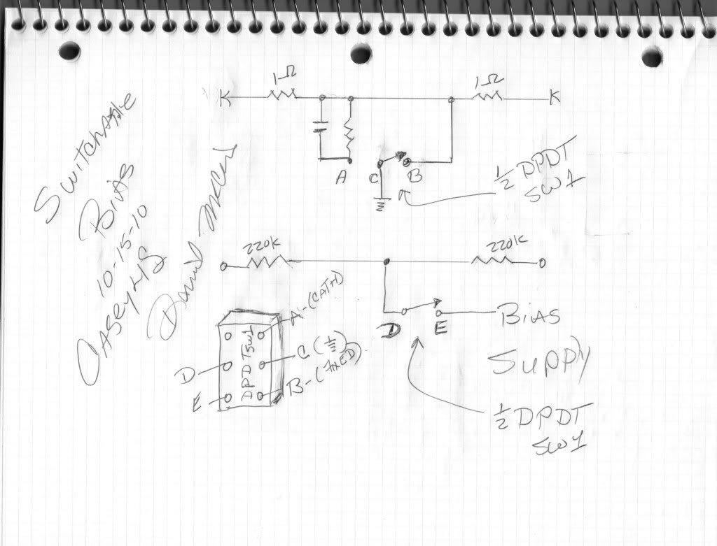
              This is how I see it, maybe it's just perspective on my part. Sometimes I get hard headed when looking at someone elses sketch. I don't have to worry about the Termolo supply on this amp. So I just simplified the switch to a way that makes more sense to me.

              DIY Links

              Tolex Tutorial
              http://www.guitarkitbuilder.com/cont...lifier-cabinet

              Chassis:
              http://www.guitarkitbuilder.com/cont...lifier-chassis

              Turret board:
              http://www.guitarkitbuilder.com/cont...d-construction

              Comment


              • #8
                Cant leave the grids floating for one thing. In cathode bias mode, the junction of the 220k resistors should be grounded.

                Disregard the SF parts on the other schematic, (the bias pot tap is the junction of the 220k), it works.
                Last edited by JoeM; 10-15-2010, 08:52 PM.
                "In theory, there is no difference between theory and practice. In practice there is."
                - Yogi Berra

                Comment


                • #9
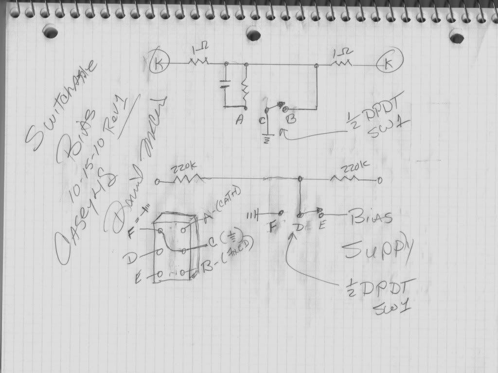
                  Ok, I can sure add that by tying the ground on the switch to the now unused lug (upper left) F.

                  Here's a fresh sketch... NOW! I understand why that switch in the London power sketch had the ground wire tied to two places on the switch.


                  I knew I could depend on some decent suggestions and comments on the forum...


                  Thanks
                  DIY Links

                  Tolex Tutorial
                  http://www.guitarkitbuilder.com/cont...lifier-cabinet

                  Chassis:
                  http://www.guitarkitbuilder.com/cont...lifier-chassis

                  Turret board:
                  http://www.guitarkitbuilder.com/cont...d-construction

                  Comment


                  • #10
                    That wouldn't quite work. you forgot to ground the junction of the 220k resistors. Easy enough to do, though. Even if you do that, the better way to switch it is the way shown in the last schematic. Why? The cathode switching on the power tubes will be quieter. In the other scheme the cathode resistor is always grounded. When the switch opens, it immediately switches in the cathode resistors. You don;t have to worry about switch bounce or switch noise or even a temporary muting of the amp while the switch is "in between" positions.

                    It is just not necessary to lift the ground from the cathode resistors. It is cleaner just to shunt around them. If you want to keep the "bias switch" totally on one half and the "cathode switch completely on the other half, just connect "A" and "C" to improve the cathode switching) and add a terminal "F" that is ground for the 220k junction to switch to. Functionally, it becomes exactly the same thing as the last schematic.

                    Comment


                    • #11
                      The sketch in post #9 is different. You are absolutly correct, you were probly typing your reply as I posted the revision. But thanks for the great reply. I don't know why I didn't see that in the first place, that's why I like posting here, you guys keep me straight.

                      Thanks again...
                      DIY Links

                      Tolex Tutorial
                      http://www.guitarkitbuilder.com/cont...lifier-cabinet

                      Chassis:
                      http://www.guitarkitbuilder.com/cont...lifier-chassis

                      Turret board:
                      http://www.guitarkitbuilder.com/cont...d-construction

                      Comment


                      • #12
                        Why don't they make amps that way? Joe said it - when amps are switchable, people almost always leave it set one way.

                        Fender makes a few amps switchable, it helps to have a ton of "features" to make an amp seem special. But those are their higher end amps. If they added that, then the cost of an amp goes up, and really it is not likely to sell many more amps by adding it.
                        Education is what you're left with after you have forgotten what you have learned.

                        Comment

                        Working...
                        X