Ad Widget

Collapse

Announcement

Collapse
No announcement yet.

Parallel 12AX7 = Boost?

Collapse
X
 
  • Filter
  • Time
  • Show
Clear All
new posts

  • Parallel 12AX7 = Boost?

    I am trying to put together an amp project for the winter.


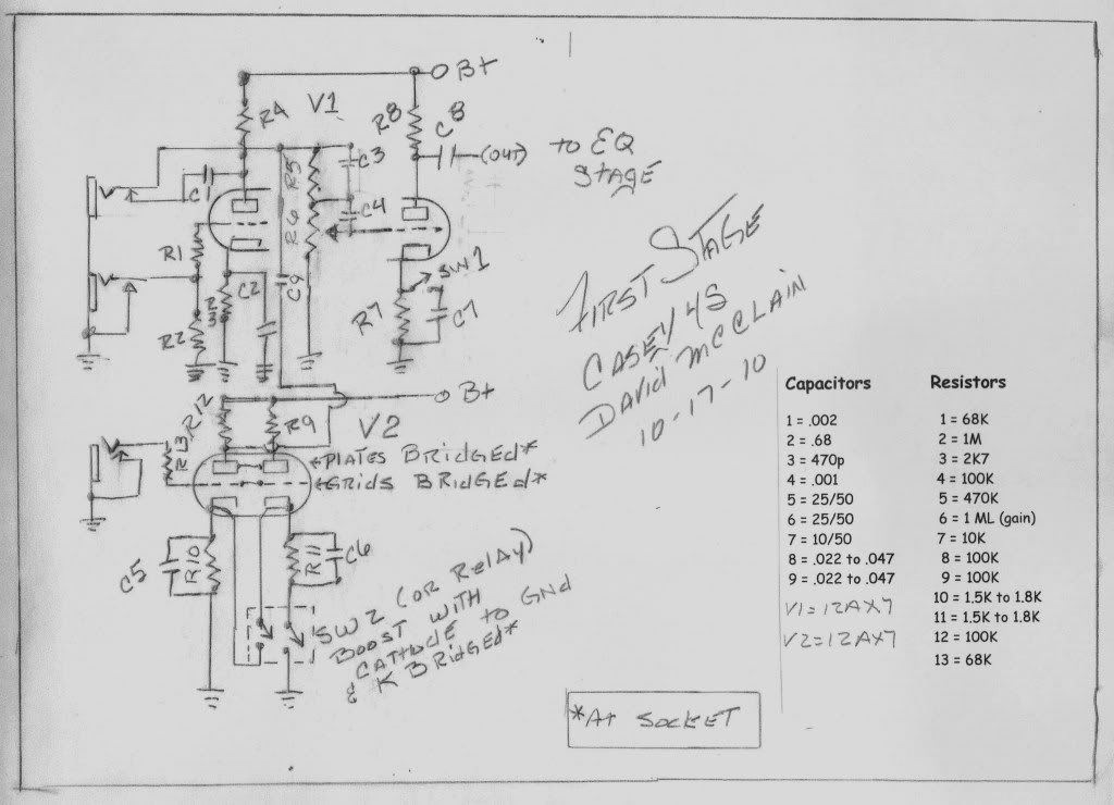
    This is my first section involving four triodes. The first two inputs (at top) are into a basic Marshall style first stage with generic Marshall values.

    Input 3 goes into it's first triode with basic Fender values on the cathode and grid stopper, but I bridged the anodes and control grids at the tube socket, with K floating. When SW2 is thrown, it connects K to ground AND bridges the cathodes which then puts the 12AX7 into parallel mode increasing gain, providing BOOST.

    I know I am going to need to tweak some values in the boost stage, I want it to sound agressive but not "over the top".

    Is this even going to work or am I pissing into the wind here?

    At C8 it goes directly into the active Bass & Treble section. (EQ?)

    Any comments or suggestions would be appreciated.

    DIY Links

    Tolex Tutorial
    http://www.guitarkitbuilder.com/cont...lifier-cabinet

    Chassis:
    http://www.guitarkitbuilder.com/cont...lifier-chassis

    Turret board:
    http://www.guitarkitbuilder.com/cont...d-construction


  • #2
    Originally posted by Casey4s View Post
    I am trying to put together an amp project for the winter. This is my first section involving four triodes. The first two inputs (at top) are into a basic Marshall style first stage with generic Marshall values. Input 3 goes into it's first triode with basic Fender values on the cathode and grid stopper, but I bridged the anodes and control grids at the tube socket, with K floating. When SW2 is thrown, it connects K to ground AND bridges the cathodes which then puts the 12AX7 into parallel mode increasing gain, providing BOOST. I know I am going to need to tweak some values in the boost stage, I want it to sound agressive but not "over the top". Is this even going to work or am I pissing into the wind here? At C8 it goes directly into the active Bass & Treble section. (EQ) Any comments or suggestions would be appreciated.
    If you go to 18watt.com there are a lot of peramp configurations there of existing amp front end designs with schematics and descriptions. Switchable cascade, parallel, plexi, JCM 800, EF86, etc as well as a lot of layouts the major botique kits use. Check it out. You can probably just lift a circuit from there. They will even discuss them with you. Just make sure you tell them it's for an 18 watt variation or they will toss your thread.
    Last edited by olddawg; 10-18-2010, 03:43 PM.

    Comment


    • #3
      Here's a revised version of my schematic, with the active Bass & treble (EQ)/ The midrange EQ (ala Ampeg V4) will be on page two. I could use a 3PST and simply bridge the anodes, grids, and cathodes in one toggle and put the two 12AX7 sections into parallel, then I wouldn't float the cathode on the second section.

      Any thoughts?

      DIY Links

      Tolex Tutorial
      http://www.guitarkitbuilder.com/cont...lifier-cabinet

      Chassis:
      http://www.guitarkitbuilder.com/cont...lifier-chassis

      Turret board:
      http://www.guitarkitbuilder.com/cont...d-construction

      Comment


      • #4
        Hi Case

        Have you got Express Schem? (Of JSchem if you are on a mac?) It makes drawing and redrawing schematics much easier.

        JSchem

        http://www.expresspcb.com/expresspcb...c_software.htm
        Building a better world (one tube amp at a time)

        "I have never had to invoke a formula to fight oscillation in a guitar amp."- Enzo

        Comment


        • #5
          Originally posted by tubeswell View Post
          Hi Case

          Have you got Express Schem? (Of JSchem if you are on a mac?) It makes drawing and redrawing schematics much easier.

          JSchem

          ExpressPCB - Free PCB layout software - Low cost circuit boards - Top quality PCB manufacturing

          I realize my schematics are a bit crude. Obviously I have never tried CAD of any kind but I'll give this a shot.

          Thanks for the link.
          DIY Links

          Tolex Tutorial
          http://www.guitarkitbuilder.com/cont...lifier-cabinet

          Chassis:
          http://www.guitarkitbuilder.com/cont...lifier-chassis

          Turret board:
          http://www.guitarkitbuilder.com/cont...d-construction

          Comment


          • #6
            Whats going on with V3a you only have 25k (R14 + R15 + R17) from b+ to ground, is this for the compression or trying to maximise current?
            Assuming V3 a 12AX7?

            For the triode switching, why not just shunt the input grid of the boost triode to ground. Just need a SPDT Switch
            R12 and R9 can be one resistor.

            Also if you share the same anode resistor for both triodes then when one triode is in use the voltage drop caused by the quiescent current in the second triode causes a constant voltage drop which effectively lowers the B+ for the first triode. Which will help in the effective gain boost.

            I think you need “mixing” resistors at the junction of C9 and C1, otherwise the output resistance those two input stages (V1a and V2) see is quite low.

            J3/V2 also needs a grid load resistor fitted.

            thats all I have for now, have to do some work.

            Mike

            Comment


            • #7
              Originally posted by guitarmike2107 View Post
              Whats going on with V3a you only have 25k (R14 + R15 + R17) from b+ to ground, is this for the compression or trying to maximise current?
              Assuming V3 a 12AX7?

              For the triode switching, why not just shunt the input grid of the boost triode to ground. Just need a SPDT Switch
              R12 and R9 can be one resistor.

              Also if you share the same anode resistor for both triodes then when one triode is in use the voltage drop caused by the quiescent current in the second triode causes a constant voltage drop which effectively lowers the B+ for the first triode. Which will help in the effective gain boost.

              I think you need “mixing” resistors at the junction of C9 and C1, otherwise the output resistance those two input stages (V1a and V2) see is quite low.
              J3/V2 also needs a grid load resistor fitted.

              thats all I have for now, have to do some work.

              Mike
              OK, I am making revisions. I added a 470K (R25) grid leak resistor, I also left the resistor to ground off of my Bass control in that drawing which is added 22K.

              I am not quite sure how to go about the mixing resistors though. I'll have to give that some thought.

              Thanks for the reply and suggestions.
              DIY Links

              Tolex Tutorial
              http://www.guitarkitbuilder.com/cont...lifier-cabinet

              Chassis:
              http://www.guitarkitbuilder.com/cont...lifier-chassis

              Turret board:
              http://www.guitarkitbuilder.com/cont...d-construction

              Comment


              • #8
                Originally posted by Casey4s View Post
                I am not quite sure how to go about the mixing resistors though. I'll have to give that some thought.
                A 220k-270k resistor in series with C1 and the junction of the jack switch contact, and another such resistor in series with C9 and the jack switch contact.

                http://www.freewebs.com/valvewizard/resistive.html
                Building a better world (one tube amp at a time)

                "I have never had to invoke a formula to fight oscillation in a guitar amp."- Enzo

                Comment


                • #9
                  Originally posted by tubeswell View Post
                  A 220k-270k resistor in series with C1 and the junction of the jack switch contact, and another such resistor in series with C9 and the jack switch contact.

                  The Valve Wizard
                  Thanks a bunch for the info and that cool link. I am revising the schematic now, I already put the grid leak resistor in place, so this is a big help.
                  DIY Links

                  Tolex Tutorial
                  http://www.guitarkitbuilder.com/cont...lifier-cabinet

                  Chassis:
                  http://www.guitarkitbuilder.com/cont...lifier-chassis

                  Turret board:
                  http://www.guitarkitbuilder.com/cont...d-construction

                  Comment


                  • #10
                    Here's the latest revision. I added the mixing resistors (R26 R27) and the grid load resistor (R25) to this version. I think it's do-able at this point but is going to take some serious tweaking during the initial fire up phase.

                    Last edited by Casey4s; 10-18-2010, 04:43 PM.
                    DIY Links

                    Tolex Tutorial
                    http://www.guitarkitbuilder.com/cont...lifier-cabinet

                    Chassis:
                    http://www.guitarkitbuilder.com/cont...lifier-chassis

                    Turret board:
                    http://www.guitarkitbuilder.com/cont...d-construction

                    Comment


                    • #11
                      Something doesnt seem right to me on the parallel stage. The plates are tied, but you have separate resistors, R12 and R9 (in parallel). Why not use a single resistor here - 47K? I dont know what happens when one cathode is floating and the plates are connected. The whole circuit is too complex IMO.
                      "In theory, there is no difference between theory and practice. In practice there is."
                      - Yogi Berra

                      Comment


                      • #12
                        Parralell input first.

                        Your grid leak resistor (R25) should go direct to ground, not to the cathode. You will probably be easist to fit this to the input jack socket.

                        I agree that you should use a single plate resistor or remove the link shown between the plates

                        You seem intent on switching the cathode for the boost, ( I would swiitch/shunt the input grid)

                        The parralell stage is set up for booming bass (big cathode bypass caps), if you are expecting anything more than clean on this input then you probably need to think about reducing the bass through the cathode bypass caps or the coupling caps

                        Cheers

                        Mike

                        Comment


                        • #13
                          Thanks Mike, and Joe, I am going to look it over today and probably try switching the input grid. I will also redo the grid leak resistor . The next section after this is going to be an Ampeg style active midrange with the inductor from a V4 - VT22. I don't even want to start on that until I get all of this part looking at least feasable. If that boost goe bust I can always disable it, but I don't see why it shouldn't work with a bit of tweaking.

                          EDIT:

                          I am also going to a single 47K plate load resistor as Joe and you have suggested. It does make better sense to go that route.
                          Last edited by Casey4s; 10-19-2010, 03:26 PM.
                          DIY Links

                          Tolex Tutorial
                          http://www.guitarkitbuilder.com/cont...lifier-cabinet

                          Chassis:
                          http://www.guitarkitbuilder.com/cont...lifier-chassis

                          Turret board:
                          http://www.guitarkitbuilder.com/cont...d-construction

                          Comment


                          • #14
                            Switching the dc operating conditions of that boost tube V2b will make an almighty noise that registers in the Richter scale, unless the user remembers to mute the vol controls.
                            My band:- http://www.youtube.com/user/RedwingBand

                            Comment


                            • #15
                              Originally posted by pdf64 View Post
                              Switching the dc operating conditions of that boost tube V2b will make an almighty noise that registers in the Richter scale, unless the user remembers to mute the vol controls.
                              Is there a realistic way to overcome that effect? I realize I may have to eliminate the boost all to gether and remove V2 alll together.

                              I am just tired of the cliche' amp builds and other peoples design. I wanted to do somtheing kinda original for a change so I borrowed some of the elements of other designs. The tone stack (V3) is RCA Baxandall, V1 is Marshall(ish), the midrange will be Ampeg V4.

                              I decided to try this boost idea because I was looking at a Fender reverb and I wondered what a parallel boost would be like based on the idea that the 12AT7 in the verb is a parallel application so I decided to try this. If it doesn't work at least I will learn something.

                              Thanks a lot for your comments and insight, I have all winter to get this thing correct, it's my keep busy winter project.
                              DIY Links

                              Tolex Tutorial
                              http://www.guitarkitbuilder.com/cont...lifier-cabinet

                              Chassis:
                              http://www.guitarkitbuilder.com/cont...lifier-chassis

                              Turret board:
                              http://www.guitarkitbuilder.com/cont...d-construction

                              Comment

                              Working...
                              X