Ad Widget

Collapse

Announcement

Collapse
No announcement yet.

Eric Barbour's 6BM8 One-Tube Reverb Imagined...

Collapse
X
 
  • Filter
  • Time
  • Show
Clear All
new posts

  • #76
    Originally posted by dchang0 View Post
    .... By leaving out the other side, it forces the amp modder to come up with a solution for recovery and mixing on his own. In other words, Barbour's "one tube reverb" isn't a complete reverb--it's a "one-tube half-reverb" or "one-tube reverb driver."
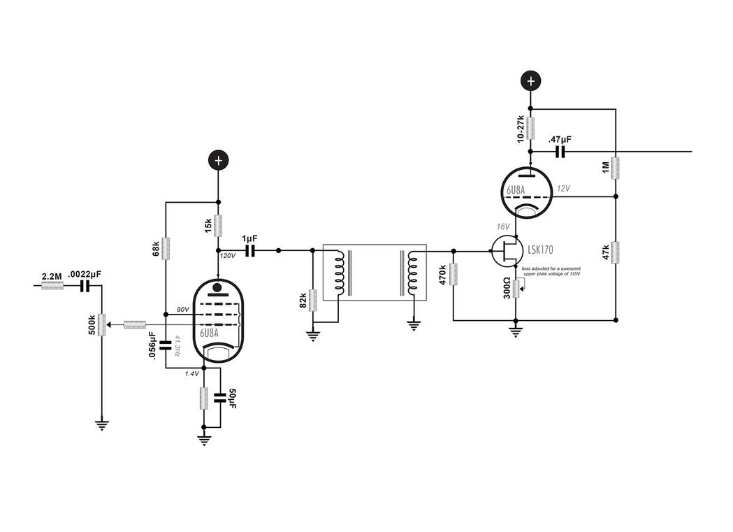
    Maybe this is a solution... The Vox V125Lead has a cascode (JFET/12ax7) input. The gain of the tube hardly matters in this configuration. You can use a lower u triode (12at7) if that's all you have. This circuit can be tweaked (see below) to give you a true voltage gain of 1000x. That gives you 5V out from 5mV in. Distortion is actually pretty low too - the 2nd harmonic is down ~50dB.

    Click image for larger version

Name:	Capture.JPG
Views:	1
Size:	78.8 KB
ID:	857621

    Anyway - I suspect you could mount the little J113 on the tube socket, so maybe this counts as 1.1 tubes...

    Something to consider ...
    “If you have integrity, nothing else matters. If you don't have integrity, nothing else matters.”
    -Alan K. Simpson, U.S. Senator, Wyoming, 1979-97

    Hofstadter's Law: It always takes longer than you expect, even when you take into account Hofstadter's Law.

    https://sites.google.com/site/stringsandfrets/

    Comment


    • #77
      Originally posted by uneumann View Post
      Maybe this is a solution... The Vox V125Lead has a cascode (JFET/12ax7) input. The gain of the tube hardly matters in this configuration. You can use a lower u triode (12at7) if that's all you have. This circuit can be tweaked (see below) to give you a true voltage gain of 1000x. That gives you 5V out from 5mV in. Distortion is actually pretty low too - the 2nd harmonic is down ~50dB.

      [ATTACH=CONFIG]58314[/ATTACH]

      Anyway - I suspect you could mount the little J113 on the tube socket, so maybe this counts as 1.1 tubes...

      Something to consider ...
      Very cool! This could be a fantastic and easy-to-fit-in solution. I could replace the daughterboard I have in my amp with a newer one that has space for the JFET on the daughterboard. Thanks for the suggestion!

      Comment


      • #78
        Originally posted by uneumann View Post
        Maybe this is a solution... The Vox V125Lead has a cascode (JFET/12ax7) input. The gain of the tube hardly matters in this configuration. You can use a lower u triode (12at7) if that's all you have. This circuit can be tweaked (see below) to give you a true voltage gain of 1000x. That gives you 5V out from 5mV in. Distortion is actually pretty low too - the 2nd harmonic is down ~50dB.

        [ATTACH=CONFIG]58314[/ATTACH]

        Anyway - I suspect you could mount the little J113 on the tube socket, so maybe this counts as 1.1 tubes...

        Something to consider ...
        This was my solution for the recovery amp in the 6U8A reverb amp I designed for my buddy's Silvertone 1474. I used an LSK170 for the JFET for its very low noise characteristics.
        .
        If I have a 50% chance of guessing the right answer, I guess wrong 80% of the time.

        Comment


        • #79
          Awesome--thank you!

          Comment


          • #80
            One other thing: If you go with the hybrid cascode, I found it much easier to add a potentiometer for the jfet source biasing resistor. This is the most critical part of the circuit to it's operation, and the differences in jfet tolerances can make it unstable to go with one resistance figure.
            It's easy enough to bias a particular fet. Adjust the source resistance for minimum current and gradually decrease the resistance while measuring the upper triode plate voltage until the plate voltage gets to the desired idle voltage set by the load line.

            you dig?
            If I have a 50% chance of guessing the right answer, I guess wrong 80% of the time.

            Comment


            • #81
              I dig--thanks!

              Comment


              • #82
                Appreciate the knowledge shared in this thread. I am looking to implement this circuit in a build of Gibson GA-5T. I’d like to understand a little better how to implement the schematic in terms of wiring the RCA jacks. If I am using grounded jacks, must I also ground the ground tab of the jack to the circuit, or is the chassis ground provided by the jack itself sufficient? So for the below circuit which I grafted into the Gibson schematic:

                Click image for larger version

Name:	IMG_1505.jpg
Views:	0
Size:	0
ID:	1007318
                So for this schematic, my layout for these jacks currently looks like the following:
                Click image for larger version

Name:	IMG_1525.jpg
Views:	0
Size:	0
ID:	1007317

                Thank you for looking in advance!
                Last edited by Splash Zone; 11-22-2024, 07:56 PM.

                Comment


                • #83
                  Originally posted by Splash Zone View Post
                  Appreciate the knowledge shared in this thread. I am looking to implement this circuit in a build of Gibson GA-5T. I’d like to understand a little better how to implement the schematic in terms of wiring the RCA jacks. If I am using grounded jacks, must I also ground the ground tab of the jack to the circuit, or is the chassis ground provided by the jack itself sufficient? So for the below circuit which I grafted into the Gibson schematic:

                  So for this schematic, my layout for these jacks currently looks like the following:


                  Thank you for looking in advance!
                  You never want to ground things twice because this can create ground loops. So in your case the chassis ground will have to be sufficient. I'd suggest the MOD tank because it has a small PCB for the connecting jacks that can be modified for shield grounding. This may or may not be important as many implemented reverbs need grounding modification to avoid ground loop hum.
                  "Take two placebos, works twice as well." Enzo

                  "Now get off my lawn with your silicooties and boom-chucka speakers and computers masquerading as amplifiers" Justin Thomas

                  "If you're not interested in opinions and the experience of others, why even start a thread?
                  You can't just expect consent." Helmholtz

                  Comment


                  • #84
                    Originally posted by Chuck H View Post

                    You never want to ground things twice because this can create ground loops. So in your case the chassis ground will have to be sufficient. I'd suggest the MOD tank because it has a small PCB for the connecting jacks that can be modified for shield grounding. This may or may not be important as many implemented reverbs need grounding modification to avoid ground loop hum.
                    Thank you! Much appreciated! I bought the Switchcraft rear-mount naturally insulated jacks. So I think these will be grounded via the chassis and so therefore I should leave the sleeve terminals unwired.

                    I have Mod tank on the way, so thanks for the tip.

                    Comment


                    • #85
                      Correct. The jacks ground via mounting and the little tab that sticks off can be used as a ground point for other circuits.
                      "Take two placebos, works twice as well." Enzo

                      "Now get off my lawn with your silicooties and boom-chucka speakers and computers masquerading as amplifiers" Justin Thomas

                      "If you're not interested in opinions and the experience of others, why even start a thread?
                      You can't just expect consent." Helmholtz

                      Comment


                      • #86
                        Chuck, thanks for taking the time to help me out! I especially appreciate his having read the whole thread a couple of times. I took close note of your point about the reverb circuit affecting the original amp’s tone, and that that must be a factor to consider when implementing a one-tube reverb circuit. In that spirit—and acknowledging that I’m approaching this with humility as a learner—would you mind taking a look at the true bypass switch I am attempting to implement here?

                        The off loop is in red, and comes through the switch to V1, pin 2 as in the original schematic. The off loop is in blue, and runs through the 500pf cap to the V2, thru the reverb circuit (much of the components removed in the drawing for simplicity), and back through the mix pot, a 27kR and back to the switch return, where the 100k mixing resistor straddles the send and return lug. I am most unsure of the 100kR position.

                        Note that I haven’t yet corrected the ground wiring in the RCA jacks. Thank you!


                        Click image for larger version

Name:	IMG_1529.jpg
Views:	0
Size:	643.0 KB
ID:	1007326
                        Attached Files

                        Comment


                        • #87
                          Sorry Splash, but it's too much work to decipher a circuit function from a layout. I'll need to see switches in place in a schematic format for an evaluation. Also, it seems your original links aren't working now? It could be something on my end but I don't think so.

                          NOTE: The schem for the GA5T on Shematic Heaven is different from the one you presented so I can't use that one for reference.
                          "Take two placebos, works twice as well." Enzo

                          "Now get off my lawn with your silicooties and boom-chucka speakers and computers masquerading as amplifiers" Justin Thomas

                          "If you're not interested in opinions and the experience of others, why even start a thread?
                          You can't just expect consent." Helmholtz

                          Comment


                          • #88
                            Originally posted by Chuck H View Post
                            Sorry Splash, but it's too much work to decipher a circuit function from a layout. I'll need to see switches in place in a schematic format for an evaluation. Also, it seems your original links aren't working now? It could be something on my end but I don't think so.

                            NOTE: The schem for the GA5T on Shematic Heaven is different from the one you presented so I can't use that one for reference.
                            Thanks for encouraging me to think this through a little more. I found some resources, did some more reading, updated my schematic to include the switch, and found a DPDT in my stash. Using my multimeter testing for continuity and resistances I’m satisfied that I have this wired correctly for true bypass…new knowledge and skills gained, thanks!


                            Comment


                            • #89
                              FWIW Gibson amps aren't known for their robust transformers. The 6bm8 draws .78A of filament current. That adds almost an amp of current draw from your filament winding. If your PT gets too hot you might consider switching to a 12dw7. Which would require rewiring the new socket but only draws .3A of filament current. Performance probably won't change much.
                              "Take two placebos, works twice as well." Enzo

                              "Now get off my lawn with your silicooties and boom-chucka speakers and computers masquerading as amplifiers" Justin Thomas

                              "If you're not interested in opinions and the experience of others, why even start a thread?
                              You can't just expect consent." Helmholtz

                              Comment


                              • #90
                                Originally posted by Chuck H View Post
                                FWIW Gibson amps aren't known for their robust transformers. The 6bm8 draws .78A of filament current. That adds almost an amp of current draw from your filament winding. If your PT gets too hot you might consider switching to a 12dw7. Which would require rewiring the new socket but only draws .3A of filament current. Performance probably won't change much.
                                Thanks for this, I did look closely at the 12DW7-style circuits as well but went with the 6BM8 because of dchang0’s success implanting in a similar single-ended circuit. I am scratch-building this and ended up going with this Hammond which can support 3A on the filament winding. So I guess maybe I’m okay: 2 amps for 2 6BM8’s and 0.3A for the 12AX7.

                                I am a little concerned that I bought a bit too much transformer for the circuit. I think I meant to buy a slightly different one rated for ~80mA current for the HT winding, but instead I got one rated for 100mA.

                                The rationale for this was that I was expecting around 25-30mA on the 6BM8 pentode, and with two triodes I was estimating mid-high 30 mA’s total. I needed a PT with a rectifier winding so I had to choose between a Hammond that was rated at around 40mA, or one which was about 2x. Since I wanted to add the reverb (another 10-12 mA), I decided to err on the side of higher rather than lower current, but accidentally got the even higher capacity transformer. I am wondering if I am going to get a much higher B+ than 275V as a result…

                                I may need to buy a different transformer but not a big deal, I will save the extra one and put it too good use somewhere else!

                                Comment

                                Working...
                                X