Ad Widget

Collapse

Announcement

Collapse
No announcement yet.

6ax5 rectifier center tap

Collapse
X
 
  • Filter
  • Time
  • Show
Clear All
new posts

  • 6ax5 rectifier center tap

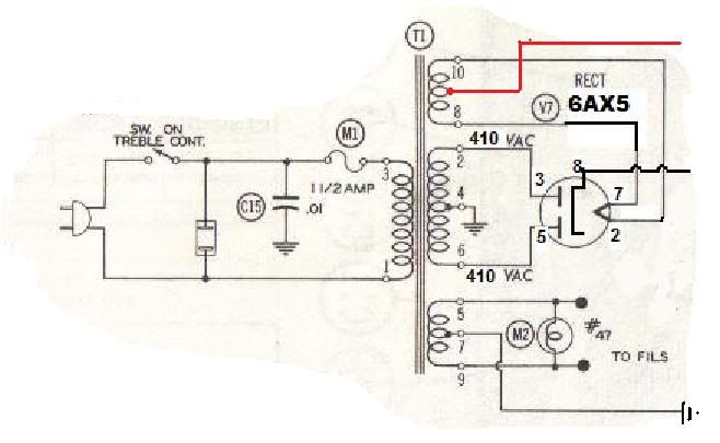
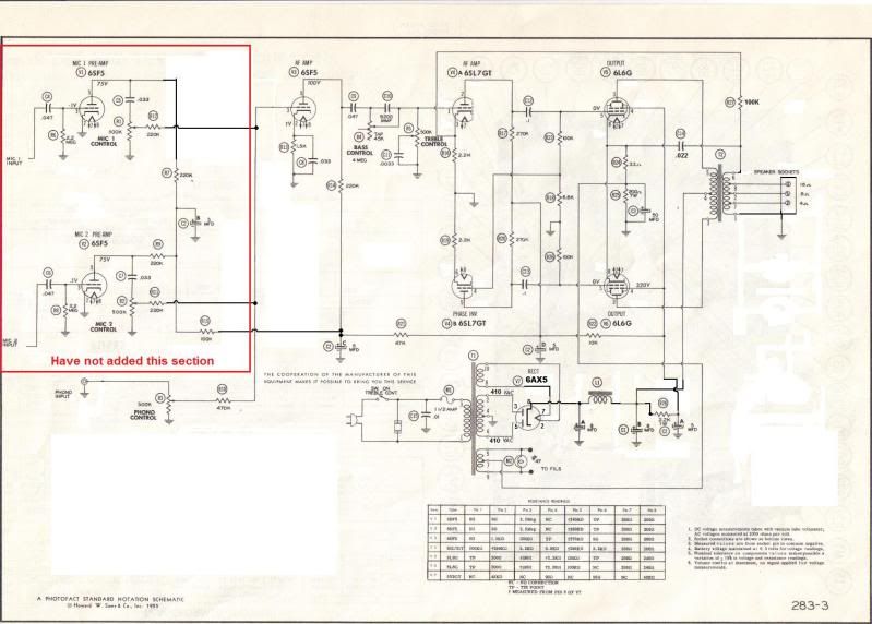
    what do i do with it. the other heater winding has a center tap on the schematic but doesnt show one for the rectifier heater. how can i make sure its a center tap for that winding.


    ive attached the the one from the rectifier heater winding(not shown) to the one from the regular heater winding CT. i know for sure not to ground it but thats all the info i can find. everything thing else is for different setups.

  • #2
    If I understand your question you have two center-tapped heater windings, one for the rectifier and the other for the rest of the tubes.

    1. You do need to ground the center tap for the rest of the tubes, or at least reference it to ground somehow.

    2. You don't necessarily want to ground the center tap for the rectifier, although the 6AX5 spec says maximum peak heater-cathode voltage is 450V. As long as your plate voltage is lower (which it appears to be), you could ground the center tap or (my recommendation) just let the winding float. You can roughly determine whether the winding is center-tapped by measuring the resistance. The resistance from the center tap to the two ends should be about the same, and the resistance from end-to-end should be the sum of the other two.

    Comment


    • #3
      Originally posted by TransLucid View Post
      If I understand your question you have two center-tapped heater windings, one for the rectifier and the other for the rest of the tubes.

      1. You do need to ground the center tap for the rest of the tubes, or at least reference it to ground somehow.

      2. You don't necessarily want to ground the center tap for the rectifier, although the 6AX5 spec says maximum peak heater-cathode voltage is 450V. As long as your plate voltage is lower (which it appears to be), you could ground the center tap or (my recommendation) just let the winding float. You can roughly determine whether the winding is center-tapped by measuring the resistance. The resistance from the center tap to the two ends should be about the same, and the resistance from end-to-end should be the sum of the other two.
      I think its the ceter tap for that winding. i dont know what else it would be. Ill double check that i have my center taps right, By let the winding float you mean just cap it and not use it.

      this is what i have goin on and in RED is what i cant find on any schematics.

      Comment


      • #4
        Yes, just cap the center tap and let the winding float, meaning it will be at whatever DC voltage it wants.

        In many rectifiers, the cathode is connected to one side of the filament, so there is no center tap on the filament winding.

        Comment


        • #5
          Originally posted by TransLucid View Post
          In many rectifiers, the cathode is connected to one side of the filament, so there is no center tap on the filament winding.
          Yes but this amp was designed with a 6ax5 and this power trans, unfortunately i cant find a schematic for it and it was all hacked up so tracing it wasnt an option. Thanks for the advice im slowly working trough this circuit and im sure ill have many more questions.

          Comment


          • #6
            actually, the 6ax5 looks like a nice rectifier...

            by the way, make sure that that secondary is not 5V/6.3V, instead of center tapped. Another way to check is to power it up and measure the AC volts between the various taps.

            Comment


            • #7
              I would use an artificial center tap on that guy, even if there is a "real" center tap on the filament winding.

              Comment


              • #8
                I don't get the question.

                The rectifier heater winding doesn;t need a center tap, what would it do? If you ground such a center tap, then you have a huge voltage between cathode and heater. The RCA says 450v. If those plates are really at 410VAC, that is at least 100v higher than that limit in DC volts.

                The rectifier is not a gain tube, is not a preamp tube, so it won;t have the opportunity to make unwanted hum currents anyway.

                410VAC is about 290VAC RMS, so any added hum from a 6v heater would disappear into that anyway. And that is what filter caps are for in the first place.

                Unlike 5v heater windings that are center tapped, this is a pure heater winding. No B+ current is drawn through it. SO no advantage there.


                WHy on earth would you connect the center tap of the recto heater winding to the other heater center tap? The main 6v winding has a CT wired to the output tube cathdoes, this provides elevation for preamp hum reduction. Now in your last drawing, you show that wired to ground instead. Why? That eliminates some of your hum reduction, and the connection to the recto heater we already discussed.

                You have added a red wire and cannot find it on schematics. Yes, because it doesn;t belong there. You can verify which winding a center tap serves by checking continuity. You do have to make sure the right ones are wired where they belong. But that center tap that is not on the schematic? Don;t wire it to anything.
                Education is what you're left with after you have forgotten what you have learned.

                Comment


                • #9
                  +1. I've always left rect. heaters floating. Never thought much about it.

                  Comment


                  • #10
                    Thank you TransLucid and ThermionicScott for your help it is appreciated.

                    I've measured resistance across both heater windings and their center taps. the resistance seems to be equal across all three wires for both windings. does that mean anything.

                    Also is there anyway to see which winding i should use for the recto vs the one for the rest of the tubes? Both having center taps and the same voltage makes it difficult to tell.

                    Comment


                    • #11
                      Your first statement seems impossible - if one of the wires is indeed a center tap, the resistance from the CT to two other ends should be the same, but the resistance end-to-end should be double. Maybe your resistance meter is not accurate enough at those low resistances. You can try powering it up and measuring the AC voltages..

                      As for your second question, it shouldn't make any difference, assuming both windings are capable of supplying the same current.

                      Comment


                      • #12
                        Originally posted by TransLucid View Post
                        Your first statement seems impossible - if one of the wires is indeed a center tap, the resistance from the CT to two other ends should be the same, but the resistance end-to-end should be double. Maybe your resistance meter is not accurate enough at those low resistances. You can try powering it up and measuring the AC voltages..

                        As for your second question, it shouldn't make any difference, assuming both windings are capable of supplying the same current.
                        Yeah my equipment is not that accurate. ill test the voltages again.

                        Comment

                        Working...
                        X