Ad Widget

Collapse

Announcement

Collapse
No announcement yet.

SE Power Amp, is it really this simple?

Collapse
X
 
  • Filter
  • Time
  • Show
Clear All
new posts

  • SE Power Amp, is it really this simple?

    I have a buddy that want's me to build him one of my amps. Only difference is, he wants a 10w power section with a single tube. I've never built a single-ended PA before, so this is new to me.

    I drew this up a few minutes ago, is it really this simple? Figured with the proper voltages I could get close to 10w out of the 6L6, right where he want's it. Fixed bias not cathode bias, since he wants it 'tight'.
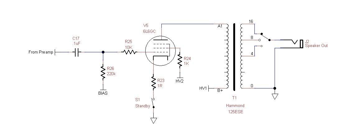

    It just seems too easy, so I want to make sure I'm not forgetting anything.

  • #2
    Originally posted by DIY_Guy View Post
    I have a buddy that want's me to build him one of my amps. Only difference is, he wants a 10w power section with a single tube. I've never built a single-ended PA before, so this is new to me.

    I drew this up a few minutes ago, is it really this simple? Figured with the proper voltages I could get close to 10w out of the 6L6, right where he want's it. Fixed bias not cathode bias, since he wants it 'tight'.


    It just seems too easy, so I want to make sure I'm not forgetting anything.
    As long as the power tranny can supply the voltage/current and the OT has the proper impedance for that voltage and current to get 10 watts out of the output tranny yes it is that simple.
    Jon Wilder
    Wilder Amplification

    Originally posted by m-fine
    I don't know about you, but I find it a LOT easier to change a capacitor than to actually learn how to play well
    Originally posted by JoeM
    I doubt if any of my favorite players even own a soldering iron.

    Comment


    • #3
      Thanks for confirming.

      Comment


      • #4
        It's basically that simple but fixed bias won't guarantee a tight output. You may need some negative feedback. The one detail you left out is the B+ voltage. With the transformer specified, you'll probably need to use a 2500 ohm primary connection which will mean no 16 ohm tap. Otherwise the B+ will be too high. Hum can be a problem, experiment with the filtering.
        WARNING! Musical Instrument amplifiers contain lethal voltages and can retain them even when unplugged. Refer service to qualified personnel.
        REMEMBER: Everybody knows that smokin' ain't allowed in school !

        Comment


        • #5
          Originally posted by loudthud View Post
          It's basically that simple but fixed bias won't guarantee a tight output. You may need some negative feedback. The one detail you left out is the B+ voltage. With the transformer specified, you'll probably need to use a 2500 ohm primary connection which will mean no 16 ohm tap. Otherwise the B+ will be too high. Hum can be a problem, experiment with the filtering.
          I'm shooting for a B+ around 350v.

          As for filtering, I was going to start with 120uF and go from there.

          Comment


          • #6
            It isn't just the cap size. Unlike a push pull amp, a single ended amp has no natural hum cancelling. Rather than install boatloads of microfarads, think more like stages of filtration - CRC or CLC.
            Education is what you're left with after you have forgotten what you have learned.

            Comment


            • #7
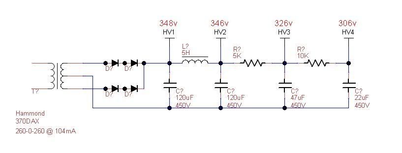
              Here is what I've come up with so far, using the Duncan PSU designer. Voltages are just an estimate.

              Comment


              • #8
                Originally posted by DIY_Guy View Post
                Fixed bias not cathode bias, since he wants it 'tight'.
                SE amps are naturally tight; I wouldn't hesitate to use cathode bias.

                Comment


                • #9
                  I think I'm going to stick with fixed bias, the transformer I have for the build has a bias tap anyway. And to use the simple poweramp only standby/mute (so the preamp can still be used for silent recording) I can't do it with cathode bias. I would assume lifting the cathode while cathode biased would be detrimental to the health of the tube :-)

                  Comment


                  • #10
                    Originally posted by SeanF View Post
                    SE amps are naturally tight; I wouldn't hesitate to use cathode bias.
                    I wouldn't make a generalization like that. The 125 ESE does do pretty well though. Since you don't have a preamp tube in the "power amp" you could try cathode bias with a little cathode feedback from one of the output taps. I also second the comment on using the 2500 ohm tap. An El34 might give you similar output with less input voltage, should that be an issue. Amps like this can be a ton of fun- built correctly they'll take almost any 8 pin power tube.

                    jamie

                    Comment


                    • #11
                      Originally posted by SeanF View Post
                      SE amps are naturally tight; I wouldn't hesitate to use cathode bias.
                      I wouldn't say tight. If they have a good sounding bottom end, it's because the lack of bass due to the average undersized SE OT cancels out the boom and flabbiness caused by the lack of negative feedback.

                      Nobody really agrees on what the subjective buzzwords like tight, flabby, farty, buzzy etc. actually mean, anyway.
                      "Enzo, I see that you replied parasitic oscillations. Is that a hypothesis? Or is that your amazing metal band I should check out?"

                      Comment


                      • #12
                        Try taking the output plate from HV2 node. That will eliminate most if not all PS hum.
                        Education is what you're left with after you have forgotten what you have learned.

                        Comment


                        • #13
                          Yes, I've never really been satisfied with the hum level from a SE amp without a choke in the main plate supply.

                          I'd also query the sanity of breaking the cathode circuit with a switch like that. The OPT is a huge inductor, and won't take kindly to having the current through it suddenly cut off. I think it would make a big pop or thump in the speaker at least.

                          I also agree that cathode bias should be fine, no need for the extra complexity of fixed.

                          But yes, apart from the 3 dozen tech weenie points made above it really is that simple.
                          "Enzo, I see that you replied parasitic oscillations. Is that a hypothesis? Or is that your amazing metal band I should check out?"

                          Comment


                          • #14
                            Originally posted by Steve Conner View Post
                            I'd also query the sanity of breaking the cathode circuit with a switch like that. The OPT is a huge inductor, and won't take kindly to having the current through it suddenly cut off. I think it would make a big pop or thump in the speaker at least.
                            It works great in my 100 watters, dead silent when being switched.

                            Comment


                            • #15
                              They're presumably push-pull, though. A push-pull OPT doesn't have high inductance in the common mode, because the fields from the DC currents in the two half-primaries cancel. So there is no big load of stored inductive energy in there. And likewise, any pop that is generated will cancel because it's in the common mode.
                              "Enzo, I see that you replied parasitic oscillations. Is that a hypothesis? Or is that your amazing metal band I should check out?"

                              Comment

                              Working...
                              X