Ad Widget

Collapse

Announcement

Collapse
No announcement yet.

Switchable rectifier bridge made of BJT's?

Collapse
X
 
  • Filter
  • Time
  • Show
Clear All
new posts

  • Switchable rectifier bridge made of BJT's?

    A friend approached me yesterday with a problem: he wants a full wave rectifier bridge that he can switch on and off.

    I thought he could just wire up 4 BJT's collector - emitters as diodes and switch the whole bridge on and off by applying a positive voltage to the 4 bases tied together.

    He wants to be able to switch the bridge on and off several thousand times as an experiment he's carrying out, so relays are likely out of the question.

    What do you think?
    Valvulados

  • #2
    I don't think they make a BJT that can handle the reverse voltage on the negative swings of the AC to be honest. Even on low voltage circuits, you hook a BJT up backwards and you let the magic smoke out.
    Jon Wilder
    Wilder Amplification

    Originally posted by m-fine
    I don't know about you, but I find it a LOT easier to change a capacitor than to actually learn how to play well
    Originally posted by JoeM
    I doubt if any of my favorite players even own a soldering iron.

    Comment


    • #3
      Then I would recommend he look at using FET's instead of BJT's.


      -g
      ______________________________________
      Gary Moore
      Moore Amplifiication
      mooreamps@hotmail.com

      Comment


      • #4
        Surely silicon controlled rectifiers (SCRs) are the tool for this job?

        Comment


        • #5
          Thanks all who replied.

          Merlin, the SCR's work ok with an inductive load? I think he's driving something related to a soldering machine, I believe it's a coil after the rectifier bridge. Do SCR's work ok for that?
          Valvulados

          Comment


          • #6
            There are a lot of fine details that need attended to, to keep the magic smoke in.

            First of all I assume it is line voltage, 110 or 220.

            If I wanted to do this quickly, I'd use an off-the-shelf solid-state relay connected in the AC feed to an off-the-shelf bridge rectifier. This should be fine with an inductive load on the DC side: the bridge rectifier will allow the load current to freewheel down after the AC is removed. SSRs also work OK switching transformer primaries: the triac turns off at zero current, so there's no stored inductive energy to smoke it.

            If I wanted to do it efficiently (the above circuit has about 1 more diode drop than needed) I'd replace some of the diodes in the bridge with SCRs. I've built a couple of controlled rectifiers before, but I'd still budget a week to get the drive issues sorted out, assess reliability, and so on.

            For low voltage, high current, a MOSFET switch on the DC side might be more attractive. But this would require a freewheeling diode to handle an inductive load.
            "Enzo, I see that you replied parasitic oscillations. Is that a hypothesis? Or is that your amazing metal band I should check out?"

            Comment


            • #7
              I'm not so sure this is the best forum to ask this question... Sure I do tend to agree with comments all the others have made here. But we don't know all the details of the "experiment", and I'm just wondering if this type of thread could be handled better on one of those solid state forums...

              -g
              ______________________________________
              Gary Moore
              Moore Amplifiication
              mooreamps@hotmail.com

              Comment


              • #8
                Originally posted by mooreamps View Post
                I'm not so sure this is the best forum to ask this question... Sure I do tend to agree with comments all the others have made here. But we don't know all the details of the "experiment", and I'm just wondering if this type of thread could be handled better on one of those solid state forums...

                -g
                I'll try at electro tech and others. Thanks.
                Valvulados

                Comment


                • #9
                  Basically yes, of course it will need some thought and maybe a couple extra diodes so currents flow the right way.
                  MosFets can be used too.
                  In fact they *are* used that way in some SMPS , they are called switched or syncronic rectifiers or something like that.
                  For really high speeds and currents they can be more efficient than diodes.
                  As of comments such as:
                  I'm not so sure this is the best forum to ask this question...
                  and I'm just wondering if this type of thread could be handled better on one of those solid state forums...
                  last time I checked *this one* could very well be
                  "one of those solid state forums."
                  I don't see the label "ultra exclusive Tube Theory and Design " anywhere on this page or anywhere else in the whole Site, for that matter.
                  Juan Manuel Fahey

                  Comment


                  • #10
                    Thanks J M Fahey, adding series diodes with the BJT's emitters is a good idea. Thank you.

                    About mooreamps' comment, I think he meant it as "we're not the most qualified folks" for solid state stuff, not as "please don't post this kind of topic here". I appreciate all the feedback I got from the folks here, invaluable information.
                    Valvulados

                    Comment


                    • #11
                      JM: Yes, they are called synchronous rectifiers. Used in SMPS for output voltages below 12V when you want high efficiency: above 12V they don't deliver enough benefit to be worth the extra cost and hassle. The main consumer application is core voltage supplies for PCs, which may be something like 1.2V at 100A.

                      As you can see, the optimum solution depends on what voltage and current level you'll be running. But for any one-off industrial or experimental type application I'd heavily recommend a solution based on off-the-shelf modules, like a SSR and bridge rectifier.
                      "Enzo, I see that you replied parasitic oscillations. Is that a hypothesis? Or is that your amazing metal band I should check out?"

                      Comment


                      • #12
                        Check smps synchronous rectifier - Google Search
                        There you will find a wealth of information.
                        The technique is so widely used that suppliers offer specific controllers for them, abbundant and for peanuts.
                        It's not exactly "an experiment".
                        You will find comments such as:
                        SYNCHRONOUS RECTIFICATION
                        .... Synchronous rectification utilizes power
                        MOSFETs to rectify the output voltage of the power transformer.
                        These MOSFETs are synchronized to the converter
                        frequency and perform more efficiently the rectification of
                        the output voltage than rectifying diodes due to the low I×R
                        drop through the channel. The N channel power MOSFET
                        offers the lowest ON resistance and is relatively inexpensive.
                        If he's trying to control an (arc/TIG/MIG) soldering machine , we are talking 20 to 60V .

                        Want to keep it in the nostalgic/vintage tube area?
                        No problem.
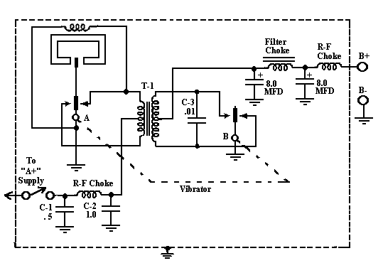
                        In *real* early times , when even a rectifier tube was something expensive , and you wanted to run your radio or amplifier out of batteries, vibrator power supplies were often used.
                        Some of these used a synchronous rectifier vibrator to save a tube:

                        If you find this facinating , as I did, check these guys restoring a 1935 Cord/Crosley (obviously tube) car radio.
                        Antique Radio Forums :: View topic - 6 Volt Positive Ground Synchronous Vibrator ?
                        OOOOPS !! Looks like we simul-posted.
                        I was doing a little research.
                        My "experiment" quote refers to post #7, not to #11 which obviously I had not read.
                        Last edited by J M Fahey; 04-20-2011, 09:46 AM. Reason: Simulpost
                        Juan Manuel Fahey

                        Comment


                        • #13
                          Well, if the guy is trying to make a square wave inverter for an AC TIG welder, that is a completely different story. The industry standard way is an H-bridge of four dirty big IGBTs on the output of a DC welding power supply. 600V IGBTs are used to stand the huge amount of noise and spikes from the arc. This is why AC TIG machines are so much more expensive than the little DC ones.

                          A bidirectional synchronous rectifier would be more efficient, because it can replace the DC welding supply's own rectifier, but I don't know if it is done. For bidirectional blocking, each element needs to be two devices back to back in series, and from a voltage drop point of view the efficiency gain isn't much compared to rectifying with Schottky diodes and inverting again with IGBTs. (Which also works out as two devices in series.) And from a control and drive point of view it is a nightmare.

                          The bidirectional synchronous rectifier is pretty much the same as the cycloconverter, which is widely studied and also has a reputation for being a nightmare to control.
                          Last edited by Steve Conner; 04-20-2011, 10:05 AM.
                          "Enzo, I see that you replied parasitic oscillations. Is that a hypothesis? Or is that your amazing metal band I should check out?"

                          Comment


                          • #14
                            Originally posted by Steve Conner View Post
                            Well, if the guy is trying to make a square wave inverter for an AC TIG welder, that is a completely different story. The industry standard way is an H-bridge of four dirty big IGBTs on the output of a DC welding power supply. 600V IGBTs are used to stand the huge amount of noise and spikes from the arc. This is why AC TIG machines are so much more expensive than the little DC ones.

                            A bidirectional synchronous rectifier would be more efficient, because it can replace the DC welding supply's own rectifier, but I don't know if it is done. For bidirectional blocking, each element needs to be two devices back to back in series, and from a voltage drop point of view the efficiency gain isn't much compared to rectifying with Schottky diodes and inverting again with IGBTs. (Which also works out as two devices in series.) And from a control and drive point of view it is a nightmare.

                            The bidirectional synchronous rectifier is pretty much the same as the cycloconverter, which is widely studied and also has a reputation for being a nightmare to control.
                            Thank you, Steve. Priceless information, appreciate it.

                            Originally posted by J M Fahey View Post
                            If you find this facinating , as I did, check these guys restoring a 1935 Cord/Crosley (obviously tube) car radio.
                            I'd never heard of that kind of rectifier, that is indeed fascinating. Thanks for sharing.
                            Valvulados

                            Comment


                            • #15
                              Originally posted by jmaf View Post
                              Thanks J M Fahey, adding series diodes with the BJT's emitters is a good idea. Thank you.

                              About mooreamps' comment, I think he meant it as "we're not the most qualified folks" for solid state stuff, not as "please don't post this kind of topic here". I appreciate all the feedback I got from the folks here, invaluable information.

                              That's not what I meant...
                              ______________________________________
                              Gary Moore
                              Moore Amplifiication
                              mooreamps@hotmail.com

                              Comment

                              Working...
                              X