Ad Widget

Collapse

Announcement

Collapse
No announcement yet.

Voltage scaling vvr and choke

Collapse
X
 
  • Filter
  • Time
  • Show
Clear All
new posts

  • Voltage scaling vvr and choke

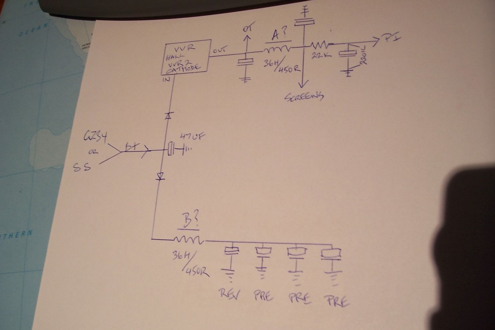
    Hi I'm trying to get some advice on the best placement for the choke and filtering on my project. The circuit is a cathode biased pair of EL34. The original circuit has
    B+ - 33uf /OT/screens - choke - 33uf - PI - Pre supply with resistors filtering etc.
    I'm installing a VVR to scale the PA and PI supply only with diodes to separate the preamp supplies. I've looked on a few boards but haven't seen any firm ideas about where the best place for the choke is. Some people have left the choke in front of the preamp supply. Others have placed it on the VVR side. Any advice on theory would be much appreciated. Cheers Joe
    Here's my schematic with a choice of choke A or B position.
  • #2
    And here's some pics of the amp itself. Trying to be a bit Matchless obviously and not make too many clangers at the same time. Tough gig. Solcat 30R pictures by kersanov - Photobucket

    Comment


    • #3
      I'm not 100% sure of the answer, but here are some thoughts:

      Often you don't need to scale the power tube plate voltage. Scaling the screen voltage can be enough, and will reduce heatsinking requirements for the VVR. It may give a slightly different tone, so maybe you want to try it both ways and see which you prefer.

      A choke directly on the VVR input terminal is probably bad. The input should see a capacitor.

      Some VVR type circuits have a capacitance multiplier thing going on that makes them effective at filtering hum, so a choke may not be required in the VVR path at all. But not all of them do: some designers want to maintain the "vintage correct" level of hum when the VVR is in use.
      "Enzo, I see that you replied parasitic oscillations. Is that a hypothesis? Or is that your amazing metal band I should check out?"

      Comment


      • #4
        I see the WR as variable regulated power supplies, so I find chokes there (*after* the regulating stage as shown) as useful as an ashtray in a motorcycle.
        Just a personal opinion.
        Juan Manuel Fahey

        Comment


        • #5
          Thanks for the thoughts. I am a hack so feel free to argue or enlighten. I can't see the choke doing much in A as the screen and OT feeds were before it in the original schematic and I probably should have another cap between the vvr and choke. I thought the VVR was a misnomer as it doesn't regulate the voltage but scales it? As the choke is smoothing the current? I'm still trying to get an idea of the best place to position it.

          Comment


          • #6
            I'd leave choke A out (it already has a resistor in series with it) and replace choke B with a resistor of say 1k.

            36H, 50 ohm DCR chokes will be big, heavy beasts, maybe 10, 20lb. Did you mean 3.6H or 500 ohms?
            "Enzo, I see that you replied parasitic oscillations. Is that a hypothesis? Or is that your amazing metal band I should check out?"

            Comment


            • #7
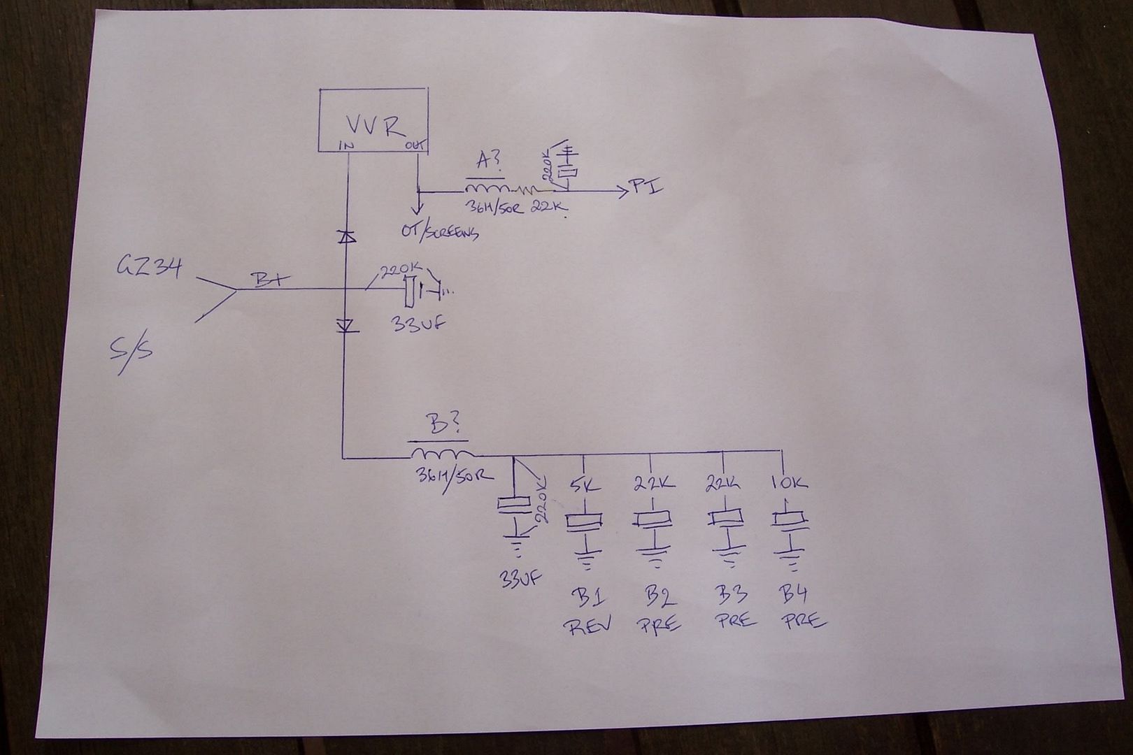
              Sorry to supply bad info on the choke, doesn't help things, I have a TDS set which has no identification markings on the choke besides "ch-30" This is the replacement set for a Hotcat30 and the only schematic around has it as "36H/450R" The choke is about the size of an 18watt OT. To clarify with the original diagram I was trying to understand if the choke was serving a better purpose if I had it in position A or position B. Having looked at a few more similar amps the screens do seem to feed off after the choke and not with the OT as in the diagram I posted. Here's an update.

              Comment

              Working...
              X