Announcement

Collapse
No announcement yet.

Direct Coupling with Zener Diodes

Collapse
X
 
  • Filter
  • Time
  • Show
Clear All
new posts

  • #46
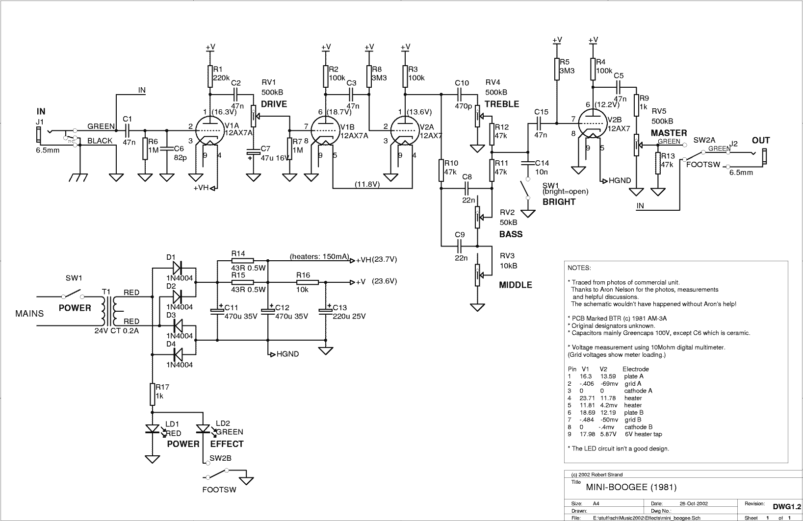
    This chat with kg has inspired me to build a rig for testing several of my older and newer 12A*7 tubes with a positive grid. Hopefully I will be able to have the scope record data on a USB dongle, something I have never been able to do so it's a good opportunity for me to learn that function.

    J M Fahey
    I've never seen preamp tubes work in the positive region, honest....I've "played" extensively with that dc-coupled pair and I shared my observations on this thread(which were ridiculed as if inexistent). Everytime the 2nd grid went positive, the tone went awful. I then pursued the reasons for this, it was the mismatched resistors, and then the previous cathode resistor. I gladly shared these results here only to be confronted by exactly the opposite conclusions from other members.

    Chuck H
    I've always treated positive grids as an avoidable ideal, yes. You nailed that....thus the reason I was so assertive. BUT I never meant to say I thought kg was throwing BS out there. But also neither am I...my past experience taught me X, kg said Y, I said "no way" but as if throwing an idea at him to see what bounced, not imposing. I left the USA 20 years ago, my English is second language, I think and write English in Portuguese so being assertive is just our semantic way of saying things, you affirm a question and then expect a contrary, which I realise now may cause the reader across the globe to interpret it as arrogance.


    kg
    Thank you for taking the time with all the links. I've always known that datasheets did plot curves for a positive grid but I always took that information as extra vendor info about the tube in exceptional condition, of what to expect in an engineering design in case the grid went positive, not something to be aiming for(that is my interpretation, subject to correction of course). With this conversation you and Steve Conner indicated that is something some folks aim for, to me that is absurd but if it's reality, then so be it. Also, to me that is news and I learned something from you and SC, I appreciate that, sorry for sounding arrogant before. I notice as well that everyone who refers to positive grid design refers to the possible authors as crazy mf's (SConner said they should be locked up, J M Fahey says feeble wicked mind, etc) so to me it is clear nobody designs for a positive grid and that what I said on this thread from my humble experience at the bench and not from 20 years in a university book, is that positive grids are to be avoided.

    My experiments with the Fender style dc-coupled pair is that the 2nd grid is always negative, as I posted above. You gave am example of a build you did, here's my latest experience: in oct/2010 for example I built an amp for a friend, simple 5f6-a based with an added volume pot before the 2nd gain stage. The 2nd grid went positive on that circuit we're discussing. It sounded like farts which is the only way I can describe it. So I remembered the matching resistors trick and matched two 100k resistors and messed with the first stage cathode resistor. Bam, perfecto tone. Am I making this up? Just 0.5 to 1V positive on that grid and the tube was clearly into cutoff, it was cutoff farting sound, same you get with a excessively negative grid.

    Back in 2005 I was at a shop with a friend and a lot of customers asked for an all tube drive pedal, no diodes, no silicon. He and I designed one using 2 tubes, where the first to second stage was direct coupled. Same thing, positive grid meant tube into cutoff region, terrible tone. Both examples are preamp tubes. To me, power tubes just handle more of this exceptional state, and are also not meant to be run positive.

    When power tube grids go positive, you are into exception mode, the grid is then competing for electrons with the plate, the only reason big tubes don't cut off immediately is because the plate is so much bigger and at a much higher potential, it is winning the battle with the grid, but the grid is robbing signal, it is competing with the plate and no longer just controlling it.

    I've since asked two friends from the local university for positive grid design examples that I could see, they both called me crazy. "Who the hell does that?". Again, thanks for taking the time to post the links and for sharing your knowledge. I hope I can contribute something to this topic in the future, I will run experiments and share my results with positive grids on preamp tubes, to have some non subjective data to show what I was describing earlier.

    exclamationmark
    Sorry for making a mess out of your thread
    Valvulados

    Comment


    • #47
      Oh well, this is getting into a desperate fight to defend the undefendable. Sigh !
      Sticking to the technical side and avoiding emotional stuff.
      1) WOW ! .... WOW again !!
      Over 300 mA from an SN7 !!!!!

      even more:
      75 mA from a common humble 12AT7 !!!!
      Mindboggling.
      I am already leaving this discussion and getting into *DESIGNING* something.
      I'm thinking into a transformer output reverb driver, with a much easier to wind transformer than the regular one (Higher current + lower "B+" = lower impedance =less turns of thicker wire) and a hybrid power amp, probably a 12AT7 straight driving a couple TIP142/147 , no feedback.

      EDIT: I almost forgot, I promised a couple schematics of positive biased preamp tubes used in commercial, successful products:
      Here they are, plus a homemade version as a bonus:

      2) MiniBoogee.
      Notice V1A/B zero biased, so at least half the input wave means positive grid.
      V2A/B positive biased, 3M3 resistor to +9V


      3) B.K.Butler Tube Driver:
      As before, the first triode is zero biased, same considerations.
      The second triode is positive biased through a 470K resistor to +12V


      4) As a bonus, Aron Nelson's Shaka tube.
      The bias pot provides positive grid voltages referred to the negative rail, where cathodes are connected.


      EDIT 2:
      Last but not least:
      I'll self-quote:
      are these last ones exotic products of a feeble/wicked mind?
      Not at all, they are respected products in their own area
      I HATE when a couple words are clipped from my statements and posted somewhere else , fully out of context, and claiming to mean the opposite of what I actually wrote.
      I find it a *very* cheap trick.

      FINAL EDIT: I notice the Forum software reduces image size (on first two examples), making them somewhat unreadable.
      If so, right click any of them, then "View/Show image", it should open full size in a new window.
      You can later go back to the original page.
      Last edited by J M Fahey; 04-29-2011, 03:07 PM. Reason: Unexpected image downsizing
      Juan Manuel Fahey

      Comment


      • #48
        OK, calm down!

        The tubes that have positive grid conditions published are, as far as I know, the ones that were used in TV vertical scan amplifiers. The commonly used circuit drove the grids positive. Nobody intended them to run as Class-A audio amplifiers like that.

        The circuits JM published are all low voltage ones: the positive grid is a band-aid to help the tube cope with the lack of B+.

        The triode section of the EABC80 is rated for use with contact potential bias. The cathode is grounded, the motivation being to save a pin. In spite of the recommended 4.7M grid leak resistor, the input impedance is only 160k. This sums up the problem with positive grid operation.

        I don't understand jmaf's concept of the matched resistors, but that doesn't mean it's wrong. I will go away and think about it.
        "Enzo, I see that you replied parasitic oscillations. Is that a hypothesis? Or is that your amazing metal band I should check out?"

        Comment


        • #49
          J M Fahey

          Looks like you have a bunch of mu-amp schematics on hand there. They rectify the signal, just like I said they would, and the tone is generally grunge rocks-in-blender stuff. BTW have you ever measured the grid to cathode voltage on some of those mu-amps? You'd be surprised in some cases.

          I am not sure "Shaka Tube" runs on positive grids, never tested one. I've never built the Tube Driver either, but mu-amp grunge rock-in-blender guitar tone rectifiers don't please me.
          Valvulados

          Comment


          • #50
            Originally posted by Steve Conner View Post
            I don't understand jmaf's concept of the matched resistors, but that doesn't mean it's wrong. I will go away and think about it.
            I measured the voltage from cathode 2 to plate 1 on that particular section of an amp that had terrible sound with humbuckers, excellent tone with Strats.... The cathode was negative.... I thought what could cause it....obviously, mismatched resistors. I took out the carbon comp resistor box, my handy LCR and matched a bunch of 100k resistors putting then on a improvised paper scale.....in the end, I took the two rightmost resistors, which meant they were the closest I found(insertion sort, for computer buffs). Bob's your uncle, -2.2V....and humbuckers sounded much better.

            I shared that experience with two experienced local technicians. They thought it was neat and that it's not really something much talked about. So I started paying more attention and found that the resistors on most Fenders matched to 1% or less....always a few volts positive on that cathode tube 2 to plate tube 1. I thought I was on to something, so I shared it here on this thread thinking it was a neat thing to share heheh. The rest is history, my Hindenburg lasted about 5 minutes

            Was a good run though, I had the chance to face some big bulls and even absorve some cheaper shots too, but I've come out alive I think. Negative grids for the win!
            Valvulados

            Comment


            • #51
              Originally posted by Steve Conner View Post
              OK, calm down!

              The tubes that have positive grid conditions published are, as far as I know, the ones that were used in TV vertical scan amplifiers. The commonly used circuit drove the grids positive. Nobody intended them to run as Class-A audio amplifiers like that.
              i beg to differ. specs are just that. how you interpret them is up to you.

              CLEARLY the datasheets show that the tube does not cease to work once the grid goes positive... that has been my singular point the ENTIRE time.

              nobody "intended" for the tubes to be used in countless ways they end up being used in MI applications. does that mean those applications are any less valid?

              Comment


              • #52
                Well, what do you know. I was organizing my bookshelf and I grab this book which is still a favorite. I open a random page and what do I see???? So I take the phrase from the 2nd paragraph and type it into Google in quotes, hoping for an OCR'd version of the book ...and voilà. Some more substance for the topic at hand.

                Basic Electronics - Google Books
                Valvulados

                Comment


                • #53
                  this has got to be the worst thread I've ever read.... I'm either laughing my ^ss off with some of these comments, or just being taken to new lows in the world of electrical theroy... I sure hope some of you don't have any plans on quitting your "day jobs"......


                  -g


                  ______________________________________
                  Gary Moore
                  Moore Amplifiication
                  mooreamps@hotmail.com

                  Comment


                  • #54
                    Well, I certainly don't plan on quitting mine, I suspect it pays a lot better than any job that involved selling things to musicians ever could.

                    KG: I totally agree with you. The electrostatic stuff inside the tube doesn't care if the grid is positive, it continues to amplify just as it did before. This is theoretically nice, but from a practical point of view, it becomes much less attractive to use as an amplifier. The grid is now a low impedance input that takes lots of current to drive it, incompatible with the high impedances elsewhere in tube electronics. Nowadays you can use a transistor to push lots of current into the grid, but now Lee De Forest would be shaking his head in disbelief, as the circuit would perform better if you used the transistor as the amplifier and got rid of the tube.

                    Indeed this is the mechanism that clips the lower half of the plate waveform in a guitar preamp: the previous stage is more or less incapable of pushing the grid positive, and if the grid can't go up any more, the plate can't come down. It follows that the output impedance of the previous stage affects the shape of the clipped waveform. If you pushed it with a transistor or similar, the clipping would probably sound quite different.
                    "Enzo, I see that you replied parasitic oscillations. Is that a hypothesis? Or is that your amazing metal band I should check out?"

                    Comment


                    • #55
                      i just consider the tube as a FET below Vg=0, and a BJT above.

                      thing is, stephen, i completely agree--there ARE plenty of reasons why people don't use tubes this way. at least not preamp tubes.

                      BUT the main one (contending with the current demands) are countered by direct coupling... which was the point of this whole thread!

                      so the second one is that non zero driving impedance causing a kink in the transfer characteristic as the grid passes that point, leading to distortion in the output.

                      this is countered by the fact that we're LOOKING for distortion, at least of the "right kind" (which is very subjective).

                      mulling the direct coupled idea around my head, i thought of two things:

                      1) the recovery from transients is instant, or at least, very much faster than your typical RC coupling.
                      2) why DON'T we use a DC servo loop to keep a bunch of cascaded stages at a reasonable point? wouldn't require much but watching the phase and making sure the NFB was only effective at very low frequencies..
                      3) something hifi guys like to do is stack power supplies, so that the level shifting doesn't have to occur in the "signal path." this requires more power supplies, though not necessarily more transformers, depending on design.
                      4) neon tubes are awesome, especially if visible to the front panel.

                      ok, so it's four things.

                      Comment


                      • #56
                        Man, been busy lately, and in five minutes I'm supposed to meet the family for a picnic! And I just wanna be in my workshack...why can't others understand;(

                        Anyways, real quickly again...
                        jmaf...I guess I jumped on you, but you have made some claims that are simply wrong, and sticking to them. So I'l try in this short time I have to explain. Tubes are not MOSFETs or even JFETs btw...

                        About positive grids:
                        The books sample you gave us jmaf is talking about that particular coupling where the two tubes are placed at completely different voltages, as if having two seperate supplies, where the b+ for the lower is the b0 for the upper. In that case there is no physical way teh grid of V2 can go positive, as it says. It has nothing to do with grids being able to go positive or if they should or not.
                        I have listened to one of my tubegeekfriend's class-A2 SE amp, where at idle the tube is biased with a positive grid, I think around 20volts, and it sounds amazing. If you read old tube books you'll find lot's of cases where grids are driven positive.

                        Btw, you say the grid becomes a diode when positive, well the cathode-plate action is also only one-way: diode.

                        As I'm sure we all know, the cathode has a cloud of free-electrons hovering in a vacuum just above the metal surface. These electrons are negatively charged. As soon as anything creating a circuit becomes positive enough those electrons will go towards that positive charge. The grids actually conduct a tiny bit (start attracting electrons) before they go positive, depending on tube structure, some a few mV below zero, some even before.
                        As soon as the grid starts to attract electrons, the circuit from grid to b+ must be able to complete the circuit for current flow, and if the impedance of that circuit is too large, the grid clips rather immediately. That's what's common in typical voltage gain stages that we usually use.

                        Study class A2,AB2, and C (radio), and also study the details in tube internals...loads of good reading available at PMillet's site.

                        About Fender and matched resistors...this is where I so rudely said 'nonsense'...and still do. After you have studied tubes you'll see that the cathodes inherently go positive in respects to the grid unless the tube is purposely used with a positive grid. It's got nothing to do with matching the resistors. Usually a common cathode stage is biased with plate at 2/3 b+, so 1/3 is over the plate resistor. (see tubecad.com for a great explanation). Anyhow, lets say we have 300V for b+, 100volts over the plate resistor, and 200volts at the plate. DC-coupling the CF simply gives a CF with roughly 100volts on it's plate, and then selecting the cathode resistor for it will depend on what idle current you want. 200kohms give an approximate 1mA, 100kohms gives about 2mA, etc. Who cares if the resistors are matched, the voltages are not matched...

                        Oh well, more later perhaps, gotta go...

                        Comment


                        • #57
                          Originally posted by mooreamps View Post
                          this has got to be the worst thread I've ever read.... I'm either laughing my ^ss off with some of these comments, or just being taken to new lows in the world of electrical theroy... I sure hope some of you don't have any plans on quitting your "day jobs"......
                          Must be tough being The Knowledgeable One and witnessing such a low level of discussion among The Commons.

                          BTW, my day job doesn't require me to quit in order to have lots of fun with positive and negative grids alike.
                          Valvulados

                          Comment


                          • #58
                            I'll try to explain real quick, am on the way out the door
                            (The circuit I used to show the concept is a generic one, and the values are not adjusted for proper use, but it'll work.)
                            The CCS pulls whatever curent you set it to, in my example that was 2mA. (If you think the zeners regulate fine, and have low enough noise, at less current, then use less current).
                            The CCS has such high impedance that you can ignore the loading effect. You can easily design a CCS that has compliance and stays constant even when swinging hundreds of volts. (In this case the swing will only be a few volts). So you can in a way ignore the CCS as it is seen by the tubes.
                            The CCS in my example pulls 2mA thru the plate resistor, 22kohms, giving a drop of 44volts, even if you unplug the tube. So basically the b+ for that tube is that dropped voltage. Now simply pick a cathode resistor value that gives you the desired plate current. I don't have time to get the datasheet now, but with a 1kohm resistor as shown, and about 80volts acting as b+ for the tube, I guess the 6922 will draw about 2mA, that's total of 4mA going thru the plate resistor, dropping 66volts, placing about 55volts on the triode's plate.
                            Since the CCS is not loading the tube, the gain is the same as if normal, the only thing different is that the voltage drop lowers the available dynamic area of the tube. ut since you are driving a small signal triode, still plenty!
                            So you have a DC coupled stage, with some drift, meaning you must oversize the cathode resistor on the DC coupled triode. This must be bypassed so you are actually back to square one with a cap after all. Using LED, diode, zener, battery or whatever on this cathode does nothing to prevent drift.
                            Still, even with potential problems, I hope you try it out...
                            ok...gotta run...

                            Comment


                            • #59
                              ah man...I gonna start ignoring you now...I hope I can, but feel there will be plenty of erronious claims in the future as well...

                              Comment


                              • #60
                                redelephant, it's ok, you didn't "jump on me", I blame it squarely on myself, as I have later seen where I mixed things up in my posts and then the confusion I myself helped create by rushing into typing and mixing up power tubes, preamp tubes, high impedance sources and so on...there were a lot of conditionals I should have included in my superlative statements. BUT, within what I tried to say, whithin preamp tubes, the context implied here(who's designing dc-couple gain stages with 300B's anyway?), I said nothing wrong though I admit I made one hell of a confusion out of it all, that is my share of mea culpa.
                                Valvulados

                                Comment

                                Working...
                                X