Ad Widget

Collapse

Announcement

Collapse
No announcement yet.

Channel switching with two input jacks

Collapse
X
 
  • Filter
  • Time
  • Show
Clear All
new posts

  • Channel switching with two input jacks

    Hi I'm trying to imagine a schematic where I can switch between a clean input jack and a gain input jack. I have a separate triode attached to each input jack and the amp has a separate phase inverter feed for each channel. There is no channel switch on the front panel so I'm hoping to implement a stereo f/sw jack to activate the optos.
    I hope to switch both the input and output of each channel and it's the input jacks that I'm struggling with. I can't see how I can have "normal" hi gain jack, clean jack operation without the f/sw then plug into one or both? jacks and then switch. Has anyone done this before or is there a schematic that I should be looking at? Hope that some parts of that made sense. Joe.
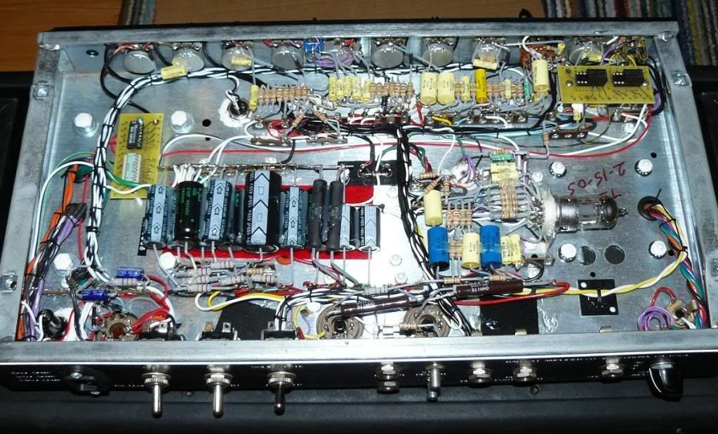
  • #2
    Check out AB channel switching for Marshall 2204 in this post
    Building a better world (one tube amp at a time)

    "I have never had to invoke a formula to fight oscillation in a guitar amp."- Enzo

    Comment


    • #3
      Originally posted by tubeswell View Post
      Check out AB channel switching for Marshall 2204 in this post
      Thanks for the response but I'm thinking the thread you linked to is for a different problem? I've built a 2204 and know how the hi-triode cascades into the low-triode, and the Park 1210 schem referenced in that thread has the same setup? with an A_B footswitch into the high gain socket and guitar into the lo socket? That seems like a good solution for the JCM But I don't have the JCM 2204 setup in my amp.
      I was hoping to switch internally but via a footswitch that doesn't A-B through the input jack. If I'm on the wrong track or missed the point please tell me.

      Comment


      • #4
        Well then you sound like you really need to set up the 'channels' with some sort of relay switching (for best results). Check out a few schematics where they have channel switching, like the PV C30/DB, or Crate v50, or SLO100* etc. This necessitates making a relay DC power supply in the amp (not too difficult) and using a couple of SPDT relays that are rated to operate at (or slightly under) the chosen DC voltage. You will also probably have to experiment a bit with the way you set up the gain stages so that you get a good OD sound especially if you are thinking of having 4 or more pre-amp stages in the signal path when the OD is engaged.

        Either that or some simple arrangement where you plug and unplug the guitar cable into different input jacks to alter the gain (but you don't sound like you want that?).

        (* the SLO uses optocouplers instead of 'relays', but it amounts to the same difference.)
        Building a better world (one tube amp at a time)

        "I have never had to invoke a formula to fight oscillation in a guitar amp."- Enzo

        Comment


        • #5
          I don't understand what you're trying to achieve here. Can you explain why a channel switching amp would need two input jacks? The whole point of channel switching is to direct your guitar through one or the other preamp.

          Maybe you want different effects ahead of the two channels? Then all you need to do is ground out or disconnect the input of the unused channel, and maybe disconnect its output from the PI, so it won't bleed or add unwanted noise when it's supposed to be off.

          If you make it so that it disconnects the unused input from the panel jack as well as/instead of grounding it, then you can also use the amp as a conventional channel switcher by jumping both jacks (or arranging the jack contacts to do this when only A has a plug in it)
          "Enzo, I see that you replied parasitic oscillations. Is that a hypothesis? Or is that your amazing metal band I should check out?"

          Comment


          • #6
            OK I was not that great trying to explain my quest. I've posted a few times about building a BadCat Hot cat for a friend. The amp I've built is working well (clean channel with reverb and dirty channel with no verb http://www.webphix.com/schematic%20h..._hotcat_30.pdf) but there is little/none in "full" schematics for the latest revision with channel switching and channel blending. The original amp started out with a clean and dirty input jack. Now they have channel switching via a f/sw off the back panel but they still have two input jacks and I'm trying to work out a way of implementing something similar. I thought this setup may have been done before on other amps so I'm trying to understand how I'd lift one input and drop the other input in, bearing in mind I've got separate triodes after each input jack. Since they state that both channels can be blended (not aiming that high) I imagine they still have separate triodes after the jacks.
            Last edited by tboy; 06-24-2011, 03:17 AM. Reason: fixed link

            Comment


            • #7
              So, according to the Bad Cat manual, the second jack does nothing when the footswitch is in use.

              I've done something similar in the past by rigging the footswitch to a DPDT relay that exchanges the two input jacks. So if your guitar is plugged into the clean channel jack, on stomping the switch it gets connected to the dirty channel, and vice versa.
              "Enzo, I see that you replied parasitic oscillations. Is that a hypothesis? Or is that your amazing metal band I should check out?"

              Comment


              • #8
                Oh! So it's just a dpdt relay/opto. I think with that germ of an idea I can see how it's wired up. Thanks for the advice guys.

                Comment


                • #9
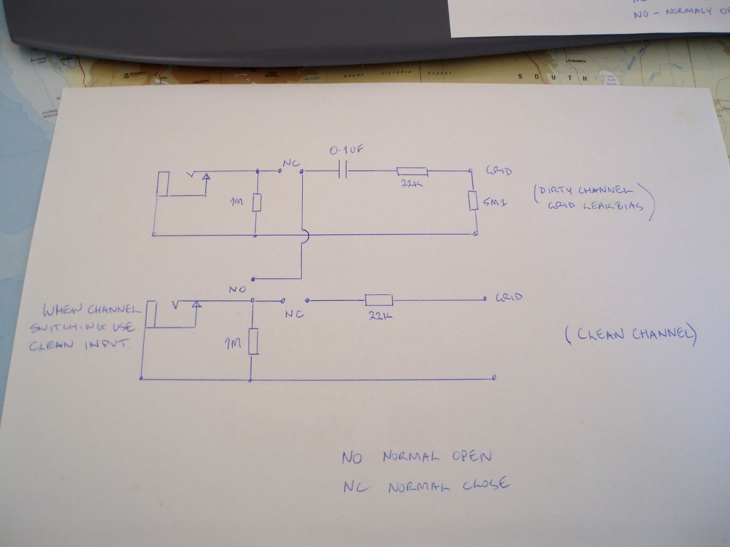
                  Ok I'm still stuck trying to work out the schematic for my input switching. I've got a start but it has a few bugs.


                  So using my drawing I've got the signal grounded via the dirty input jack all the time (when the dirty channel is engaged). Plus I've got the 1meg circuit reference in parallel (when the dirty channel is engaged) at 500K which may or may not be an issue. Any advice would be great as I still can't see a schematic on the net that is the same as this setup? Just single input jack switching.

                  Comment


                  • #10
                    You do know this problem could be solved with a Boss line selector in front of the amp, easy.

                    If you just had a single input jack you could just use a relay to mute the PI input you don’t want or have them both on

                    For the set up you have here though I would use a DPDT relay, so that the unused triode grid is grounded, reducing noise

                    Comment


                    • #11
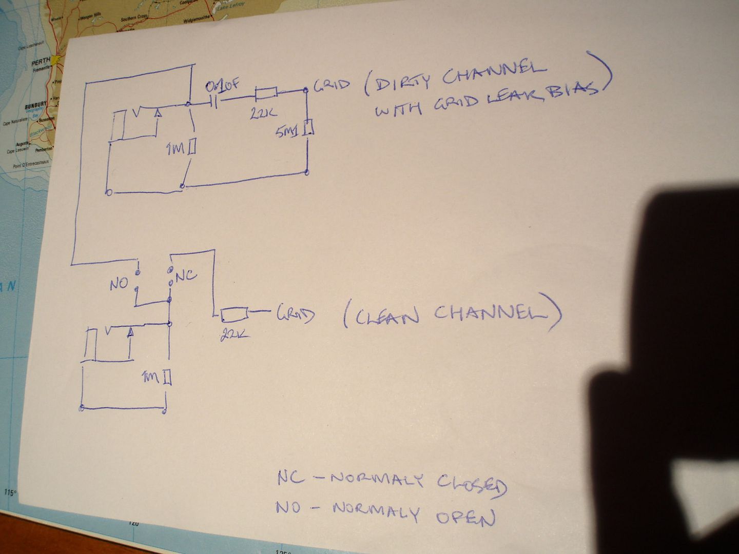
                      It's not a very common setup is it? All I can see in an original unit is the DPDT? relay sitting over the input jacks.

                      BUT! I had another think about lifting the ground on the gain input and drew this. If anyone can see issues please advice TIA.


                      I think I'll try this and see what the noise levels are like before contemplating lifting the phase inverter inputs.

                      Comment

                      Working...
                      X