Ad Widget

Collapse

Announcement

Collapse
No announcement yet.

Single ended output through push pull transformer

Collapse
X
 
  • Filter
  • Time
  • Show
Clear All
new posts

  • #16
    Originally posted by Chuck H View Post
    Just for the sake of argument... What's wrong with Gary's idea? I assume by his post that his idea is something like:
    Ground the grid on one tube.
    Heat the bias.
    Reduce drive voltage to the operating tube.

    Would this do anything to correct the operation for class A? Balance currents, etc?
    Nothing in particular wrong with it. That is what I was describing here:

    There is a way to cheat. You can run effectively Class A single ended if you use an output tube on half the primary and any means whatsoever to pull and equal idle current through the other half-primary. This idle side just pulls the transformer's flux back away from saturation and prevents the necessity of gapping. In effect, the idle side pulls the tranformer's magnetic flux back to zero to let you not have to gap the core.

    This can be two tubes if you bias both output tubes to Class A idle currents but provide signal to only one grid. That's a horrible waste of a tube on the "idle" side. It makes more sense to use a power transistor or power MOSFET to pull a constant current through the "idle side". I think there was a commercial amp that did either the idle tube or idle current source. Can't remember the name now.
    I have a dim memory that the commercial amp folks I mentioned patented the idea, but it's been a long time ago. Seems like they had a trademark that was initials and started with "K", but I can't be sure. They were doing the same Class A PP to/from Class A SE switching as I remember.

    The point is, if you're already running in class A with an OT which is designed for class A currents, then you can just ditch the drive to one tube and let the other tube run class A all by itself, and it's fine. The tube which is idling provides the same DC balance for the output transformer as it did when it was active, but all the signal swing is done by the tube which still gets signal. Tinkering with the bias point in single-tube mode may or may not be needed - there's nearly always some tinkering to be done.

    In response to your question, it actually works better than an OT specifically designed for single ended use in some senses. That's because the offset side pulls the core back to the middle of the BH curve and lets the remaining tube at least potentially work the whole BH curve in the OT if everything is set up just right. That means the transformer can be smaller than a real SE transformer for the same power and low frequency response. I suspect the reason it was never done in the "Golden Age" is that you need a current source for the no-signal side because a resistor there will load down the active side, wasting more power. And if you put a tube there, why not get the vastly larger power from class A push pull?
    Amazing!! Who would ever have guessed that someone who villified the evil rich people would begin happily accepting their millions in speaking fees!

    Oh, wait! That sounds familiar, somehow.

    Comment


    • #17
      It was 6 watts Class A, 36 watts Class A/B, R.G....

      -g
      ______________________________________
      Gary Moore
      Moore Amplifiication
      mooreamps@hotmail.com

      Comment


      • #18
        Originally posted by mooreamps View Post
        It was 6 watts Class A, 36 watts Class A/B, R.G....
        Yes, you said that. Is there a point to your saying it again?
        Amazing!! Who would ever have guessed that someone who villified the evil rich people would begin happily accepting their millions in speaking fees!

        Oh, wait! That sounds familiar, somehow.

        Comment


        • #19
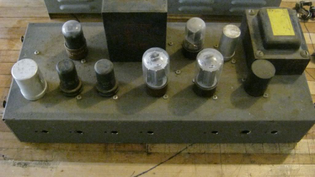
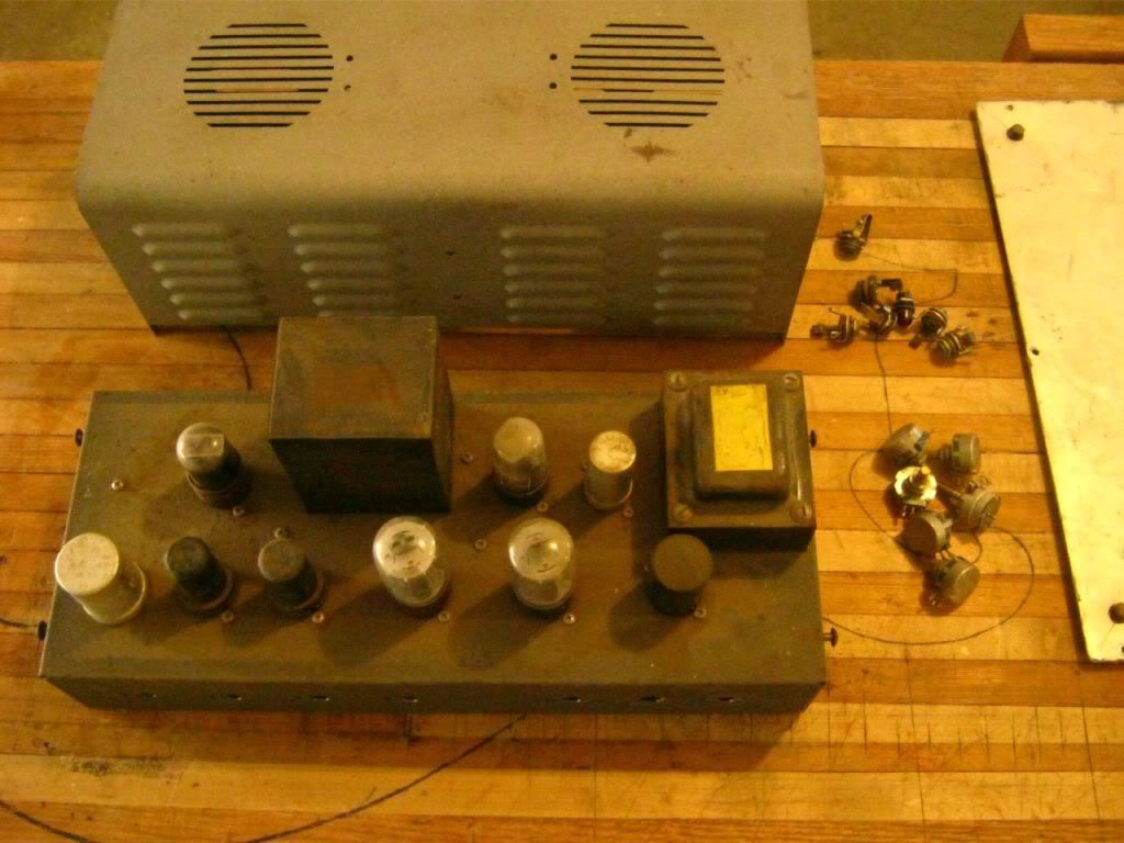
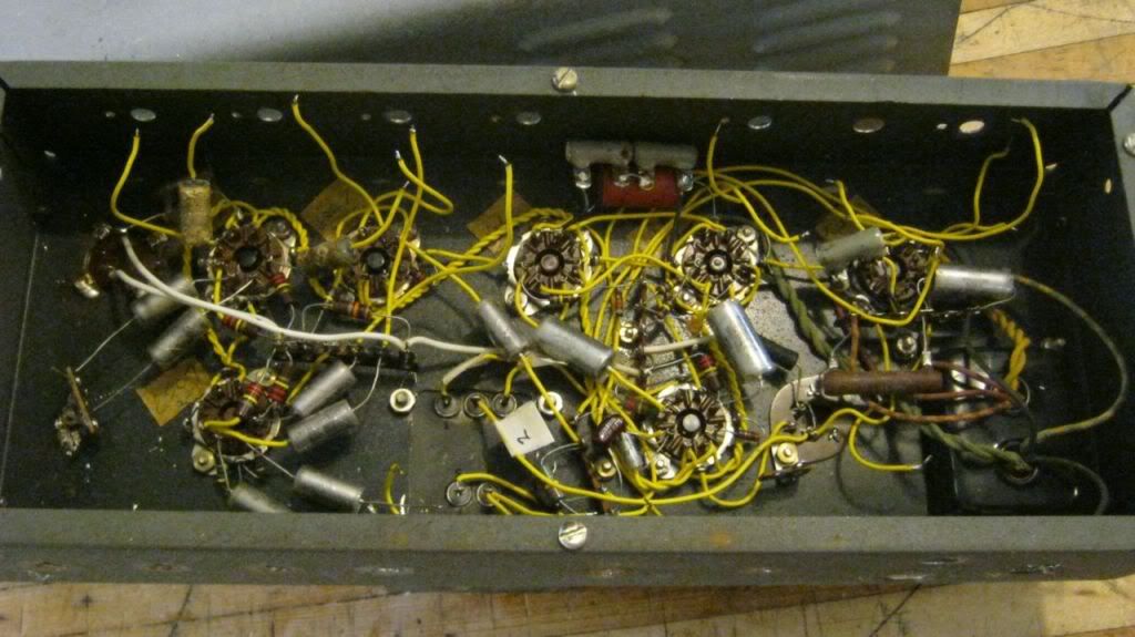
          O.k., here are some pics. I want to make some progress with it so I stripped the chassis to prep for a fresh coat of paint. I started investigating the power transformer by attaching my signal generator to the primary and setting it at 60hz and 12 volts. The secondaries all had appropriate voltages, with the rectifier plate-to-plate reading 76.6.

          I've never designed a power supply from scratch like this before. Am I right in thinking this will give me 540 volts B+ with solid state rectification? I was thinking about a tube rectifier, but it looks like a pair of 6550s would need two of them.


          Comment


          • #20
            Hi all,

            I'm starting a new project and have some doubts and maybe you could help me or give me some hints!

            I want to build a tube amp and I already have some parts and "wanted" specs:


            1- I have a OT push-pull 25 watts with several output possibilities (1,25 2,5 5 7,5 10 14 18 30 75 100 125 300 350 400 450 500 ohms), I tested it and measured 6,2 Kohms on the primary. (also, i can use a mis-matched output to obtain different impedances at input)

            2- I have a power transformer with 6,3VAC and 230-0-230 VAC

            3- I would like to use a pair of 6V6s in push-pull Class A

            4- I want a single-ended capability

            Here are my questions:

            1- How to bias the power tubes/valves to achieve Class A push-pull (even with the single-ended option)?
            2- How to estimate the needed input swing to drive the output stage?
            3- How to design the splitter to accomplish this?

            Thank you for your help in advance!

            Comment


            • #21
              Originally posted by andresbianco View Post
              3- I would like to use a pair of 6V6s in push-pull Class A
              4- I want a single-ended capability

              Here are my questions:

              1- How to bias the power tubes/valves to achieve Class A push-pull (even with the single-ended option)?
              2- How to estimate the needed input swing to drive the output stage?
              3- How to design the splitter to accomplish this?
              You can have Class A PP, but what do you mean by "with the SE option"? If you do not want to have cross-over distortion ("SE operation"), then Class A PP accomplishes that. The drive required depends on your operating conditions, i.e., the plate/screen voltage and the load, so if you have 6.2k Ra-a, each half of the PP would see 3.1k, draw a load line for center bias (Class A), then that's the bias voltage required, double that and you get the peak-to-peak drive requirement. For the PI, it is no different from one used by other PP stages, just pick your favorite topology.

              Comment


              • #22
                Originally posted by jazbo8 View Post
                You can have Class A PP, but what do you mean by "with the SE option"? If you do not want to have cross-over distortion ("SE operation"), then Class A PP accomplishes that. The drive required depends on your operating conditions, i.e., the plate/screen voltage and the load, so if you have 6.2k Ra-a, each half of the PP would see 3.1k, draw a load line for center bias (Class A), then that's the bias voltage required, double that and you get the peak-to-peak drive requirement. For the PI, it is no different from one used by other PP stages, just pick your favorite topology.
                Thank you for your quick answer!
                "with the SE option"= not to provide signal to one grid (i.e. with a switch or pot), so one tube is working and the other one is just idle.

                When you say "draw a load line", you mean over the 6V6 pentode curve, right?

                PI? sorry i'm new in this and english isn't my mother tongue!

                Thanks again !

                Comment


                • #23
                  If you have Class A PP, you do not need to "shut off" one side as some of the posts above suggested - in those amps, the output stage normally operates in Class AB mode, so by turning the drive off on one side only, they end up with Class A operation. Yes, you can draw the load line on the 6V6 plate characteristic chart. "PI" is just short for phase inverter. BTW, your English is excellent.

                  Comment


                  • #24
                    Originally posted by jazbo8 View Post
                    If you have Class A PP, you do not need to "shut off" one side as some of the posts above suggested - in those amps, the output stage normally operates in Class AB mode, so by turning the drive off on one side only, they end up with Class A operation. Yes, you can draw the load line on the 6V6 plate characteristic chart. "PI" is just short for phase inverter. BTW, your English is excellent.
                    Maybe I'm a little confused: even in Class A (push-pull) some even-order harmonics are cancelled out due the balanced OT primary, right? I just aim to get them back.

                    Also, in the example you mentioned (class AB to single ended), if you "shut off" one side you only have 180º of signal, right? so, a lot distortion too? or they are moving the operation point as well?

                    Another question, if you bias for Class AB, you need to draw a load line with 1/4 of the Raa load, right?

                    Thanks again!

                    Comment


                    • #25
                      Originally posted by andresbianco View Post
                      Maybe I'm a little confused: even in Class A (push-pull) some even-order harmonics are cancelled out due the balanced OT primary, right? I just aim to get them back.
                      That's correct, if you want to get the 2HD back then you may be better off with a straight SE design - you make a full circle.

                      Also, in the example you mentioned (class AB to single ended), if you "shut off" one side you only have 180º of signal, right? so, a lot distortion too? or they are moving the operation point as well?
                      No, when you shut off one side, the other side see the full 360º, otherwise, the amp would become a half-wave rectifier, but that is not the case here.

                      Another question, if you bias for Class AB, you need to draw a load line with 1/4 of the Raa load, right?
                      Well, for Class AB, the load line is actually a composite curve, but for simplicity, you can draw two load lines - one at 1/4 Ra-a for Class B and one at 1/2 Ra-a for Class A. But if you bias the output for Class A operation in your proposed amplifier, you do not have the Class B load line, as the tubes never reach cut off.

                      Comment


                      • #26
                        Originally posted by jazbo8 View Post
                        That's correct, if you want to get the 2HD back then you may be better off with a straight SE design - you make a full circle.
                        Well, the fact here is that I already have a PP OT, so is not gaped for SE topology.


                        Originally posted by jazbo8 View Post
                        No, when you shut off one side, the other side see the full 360º, otherwise, the amp would become a half-wave rectifier, but that is not the case here.
                        I mean in the case of pure Class AB (not what I want to do), if it was designed in order to each tube only amplify one side, if you shut off one side: don't you get a half-wave rectified output?

                        Originally posted by jazbo8 View Post
                        Well, for Class AB, the load line is actually a composite curve, but for simplicity, you can draw two load lines - one at 1/4 Ra-a for Class B and one at 1/2 Ra-a for Class A. But if you bias the output for Class A operation in your proposed amplifier, you do not have the Class B load line, as the tubes never reach cut off.
                        Ok. I just have an extra question regarding plate curves: If I have 325 VDC in B+, this is not the plate voltage due the drop in the primary, how do I pick a curve to draw the load line? I mean in the curve we have specified the Plate voltage which is unknown for me yet.

                        Thanks

                        Comment


                        • #27
                          I mean, I know in DC is not drop in the primary (theoretically) but if you have Rk you get a drop there.

                          Comment


                          • #28
                            Originally posted by andresbianco View Post
                            I mean in the case of pure Class AB (not what I want to do), if it was designed in order to each tube only amplify one side, if you shut off one side: don't you get a half-wave rectified output?
                            In class AB each side amplifies 60 to 70% or so of the wave depending on exactly were bias is set. If each side only amplified 50% or the wave, that would be class B. If the bias is class A, each side amplifies 100% of the wave.
                            Last edited by loudthud; 08-19-2014, 03:55 PM. Reason: Typo
                            WARNING! Musical Instrument amplifiers contain lethal voltages and can retain them even when unplugged. Refer service to qualified personnel.
                            REMEMBER: Everybody knows that smokin' ain't allowed in school !

                            Comment


                            • #29
                              Originally posted by loudthud View Post
                              In class AB each side amplifiers 60 to 70% or so of the wave depending on exactly were bias is set. If each side only amplified 50% or the wave, that would be class B. If the bias is class A, each side amplifies 100% of the wave.
                              Sure, my bad! 360º > Class AB> 180º.

                              The other question regarding plate curves: If I have 325 VDC in B+, this is not the plate voltage due the drop in Rk, how do I pick a curve to draw the load line? I mean in the curves we have specified the Plate voltage which is unknown for me yet. Maybe, I could pick a value taking "no drop" in Rk and the difference is not so big, right?

                              Thanks

                              Comment


                              • #30
                                Take a look at Merlin's page for a quick tutorial.

                                Comment

                                Working...
                                X