 Tweet
Tweet
Most plate curves you find in tube manuals assume that the cathode is grounded.
-
WARNING! Musical Instrument amplifiers contain lethal voltages and can retain them even when unplugged. Refer service to qualified personnel.
REMEMBER: Everybody knows that smokin' ain't allowed in school ! -
Given that each valve sees a load of 1/2 the transformer impedance in push pull class A, what happens when you cut the grid signal off from the other tube? I'm assuming it then sees a 1/4 impedance? I know some hi-fi folks use push pull transformers as single ended transformers by running a dc bias current through the unused windings (which is essentially what happens in this case).
Another point comes to mind... What happens in the real world when your load line extends past 2*HT? For example, if you attach a 16 ohm load onto an amplifier designed to run at 8 ohms, how does the transformer react?Comment
-
Thanks all for the info!Originally posted by jazbo8 View Post
So, the aim is Push-pull Class A with 2 6V6s, B+=325 and OT= 6,1Kohm (it has several output options from 1,25 ohm to 500ohm)
1- I draw a load line of 3,1Kohm (1/2 Raa of the OT) from the point 325V (my B+) and Ib=0.
2- I draw a vertical line in Vp=325V
3- I draw a load line with the same slope crossing the the above in Ib=40ma (dissipation P=325x0,04=13 watts)
4- Estimate Vg=-14V
5- Compute Rk=14/0,04=150 ohms and rated power 1 watt > VxI=14x0,04=0,56 watts
6- I have an output swing between 125V and 450V centered in 325V (positive 200=325-125 and negative 125=450-325), which isn't symmetrical (if I want more symmetric swing, I need to increase Ib and the power dissipation in the plate is above the maximum. Or try another slope using other mismatched tap in the OT secondary)
7- Power output P = (HT-Vmin) x Ipeak / 2= (325 - 125)x0,105/2=10.5 watts
Am I in the track? Or I screw it up?
Thanks!
Comment
-
I did not go through your steps in detail, but I think you got the basic concept. However the chart that you used is ONLY applicable for Eg2=250V, it B+ = 325V, then all the plate curves need to be shifted up by a constant, the amount of which can be found in Radio Designer's Handbook (RDH4).
Going back a bit, you said:
It is worth noting that ONLY the 2HD of the output stage itself is cancelled by the push-pull action, whatever is generated by the previous stages still appears on the output.Maybe I'm a little confused: even in Class A (push-pull) some even-order harmonics are cancelled out due the balanced OT primary, right? I just aim to get them back.
Slightly OT, it seems that you want to get more 2HD or perhaps higher distortion in general, yet you choose Class A push-pull, which generates the lowest distortion of all the output topologies...Last edited by jazbo8; 08-19-2014, 06:10 AM.Comment
-
No as stated above, each tube of class A push-pull sees 1/2 of the Ra-a. Shutting off the other tube does not change anything.Originally posted by exclamationmark View Post
This has been well covered by Fritz Langford-Smith and Patrick Turner, both gents from your neck of the woods. A quick search will give you all the answersAnother point comes to mind... What happens in the real world when your load line extends past 2*HT? For example, if you attach a 16 ohm load onto an amplifier designed to run at 8 ohms, how does the transformer react?
Comment
-
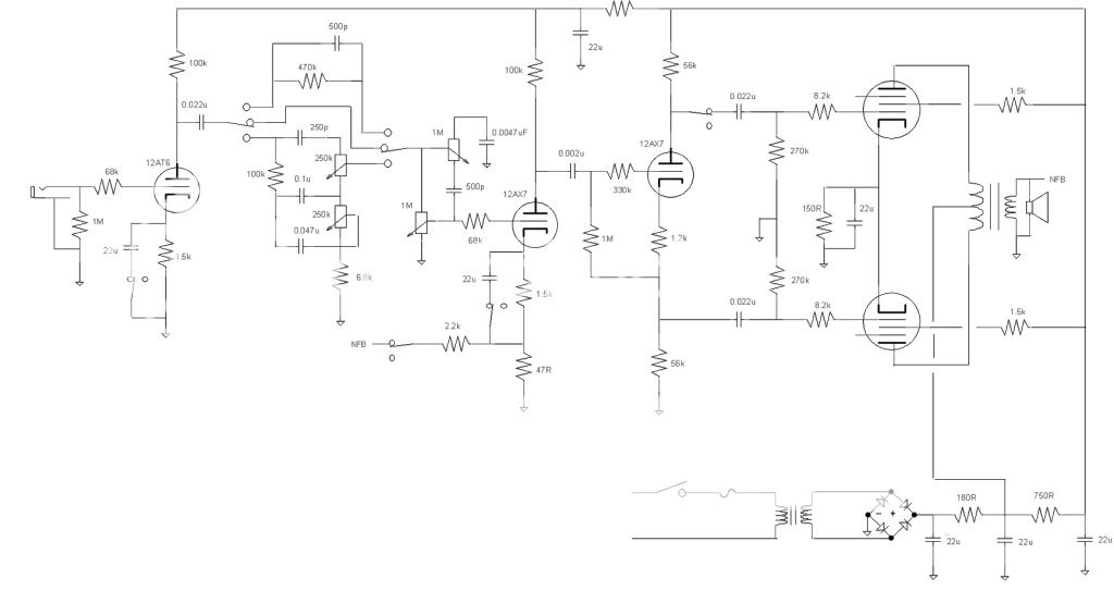
Check out the "BODY" control on the Kevin O'Connor's London Power "Standard" Amp.
It effectively allows you to pan between full push pull and single ended.
Cheers,
Ian
P.S. Ignore my scribble on changing the cross line "LIMIT" to dual 470K ganged. On my build I did that, but it eliminated the "BODY" control which is not what you want to do.Comment
-
First amp I built used 6AQ5's was Class A P-P and I had a switch to interrupt the drive to one side. Keep in mind the drop in volume is really not all that much from P-P operation.
Comment
Comment