Ad Widget

Collapse

Announcement

Collapse
No announcement yet.

Jcm800 Downscale

Collapse
X
 
  • Filter
  • Time
  • Show
Clear All
new posts

  • Originally posted by Alan0354 View Post
    I read you talk about 70V line transformer, so I pull out the 70V. For 30V, it is that much lower. I just read the posts on this thread, I have not done any of these, but you'll notice they bias very differently from your schematic. All I said is read to posts on this thread, change accordingly so you can hit it in the ball part to start.
    Oh, sorry about the 70V should have picked up on that, sometimes I miss the obvious. The 70V transformer is originally for sound distribution in schools, hospitals, and the like. They supply the audio at the 70V level and use transformers to tap off how much power they want the speaker to dissipate.

    70 Volt Sound Distribution System - Alectro Systems Inc.

    Comment


    • Originally posted by printer2 View Post
      Oh, sorry about the 70V should have picked up on that, sometimes I miss the obvious. The 70V transformer is originally for sound distribution in schools, hospitals, and the like. They supply the audio at the 70V level and use transformers to tap off how much power they want the speaker to dissipate.

      70 Volt Sound Distribution System - Alectro Systems Inc.
      Nothing to sorry about. I am not trying to give you advice as I am still learning tubes....particularly low voltage circuits. I just suggest to read over the post and the links as they really went into this deeply. I read through most, but I don't claim to absorb all of them.

      Comment


      • Here's a link I found (via SS guitar): Sopht amps - Home dealing with low voltage tube amps using low voltage tubes.
        Not sure if it's been mentioned in this post already, if so my apologies.
        Thought I'd mention it as the post seemed to be getting back on topic, I mean off tangent .
        Originally posted by Enzo
        I have a sign in my shop that says, "Never think up reasons not to check something."


        Comment


        • Originally posted by Alan0354 View Post
          What you have here is a typical old Marshall schematic designed for high B+. Read some of the posts that have schematics or links, they left out the cathode resistors and bias a little differently. You are using 70V supply, higher than what they are talking about, but it is still low, you want to follow some of the suggestions.

          It is a bad idea not to have any sort of ground plan backing and just nail on wood. If you are not familiar with electronics, not only you'll have noise pickup, you likely run into ground loop problem because it is so easy to wire the ground the wrong way and create ground loop. At least put copper foil on top of the wood. Buy wide copper tape nd tape on the wood to create a ground plane to simulate the metal chassis. Also, even if you get this going, you are going to travel around with high voltage wires exposed?
          There is really nothing new or hasn't been done in guitar amp design, so the topology will be familiar to us all, but making a new design work and sound good is not easy, especially at low voltage, I think for bread-boarding purpose, "nail on wood" is pretty much par for the course, and many of us do it before committing the build to metal chassis and neat wiring, etc. because many designs are not even worth keeping. Anyway, Printer2 has already done some tests with the 6AU6's at low voltage and was impressed enough by the sound he got out of it, so IMO it is as good a place to start as any (and that I have a bunch of those tubes). Also, the B+ is 30V (if I am reading it right), the 70V line transformer refers to the OPT not the PT, i.e., 500R:8R.

          This being one of the most popular thread at MEF, so it would be a shame if we can't even come up with a decent sounding, practical design even if we are working with the ridiculously low operating voltage...

          Jaz

          Comment


          • Currently working on a lower voltage (150V rather than 40V) SE amp with a 6AQ5 for the output into a 2.5k 2W OT from an old line powered 50C5 tubed amp. The preamp is 95% a JCM800. Never played with this circuit so it is a learning experience. I am making it for a guy at work to try, he wanted a 'brown' sounding amp for bedroom practicing. Would make more sense using a 6CU5 but I don't have any yet and I am curious if the 6AQ5 will do a watt at this low voltage.

            Trying to figure out the gain of each stage and where it starts to clip also what the maximum clean and clipped voltage out is. So far I am getting about 1/8 watt, may not sound like much but through a Warehouse ET-65 (98dB) it is about comparable to an acoustic guitar, cranked it is reasonably louder. Maybe not everyone's cup of tea but I can see it fitting in with an apartment dweller that does not plan on moving.

            Comment


            • Originally posted by printer2 View Post
              Currently working on a lower voltage (150V rather than 40V) SE amp with a 6AQ5 for the output into a 2.5k 2W OT from an old line powered 50C5 tubed amp. The preamp is 95% a JCM800. Never played with this circuit so it is a learning experience. I am making it for a guy at work to try, he wanted a 'brown' sounding amp for bedroom practicing. Would make more sense using a 6CU5 but I don't have any yet and I am curious if the 6AQ5 will do a watt at this low voltage.

              Trying to figure out the gain of each stage and where it starts to clip also what the maximum clean and clipped voltage out is. So far I am getting about 1/8 watt, may not sound like much but through a Warehouse ET-65 (98dB) it is about comparable to an acoustic guitar, cranked it is reasonably louder. Maybe not everyone's cup of tea but I can see it fitting in with an apartment dweller that does not plan on moving.
              Line power as in no PT, right? Be careful with it, it's easy to get shocked...

              Anyway, I'd like to work backwards from the output, I like to know (and learn) how to properly bias the PA, and here is what I came up with, so guys, please give me some feedback or at least put me on the right track - the 6W6 in Class AB2 PP with B+ of 40V, chose the triode mode because the screen current is quite large at such low plate voltage, I have not calculate the Po or THD (got to head off to work now...), but hopefully it is in the right ballpark.

              To drive the PA to AB2, I think a FET source follower will do the trick, so assume for the moment that the source impedance is very low...

              Click image for larger version

Name:	6W6 Triode Curves.gif
Views:	1
Size:	63.5 KB
ID:	826830

              Jaz
              Last edited by jazbo8; 09-19-2012, 03:02 AM. Reason: Add Source Follower

              Comment


              • Transformer was from a line powered amp found at the side of the road, all that was of worth was the sockets and the transformer. Now thinking of doing the Marshall preamp with a SS power amp. Once I finish it I'll get back to this one.

                The above schematic is missing a few capacitors, mainly done to give an idea what is in store.

                Comment


                • Originally posted by printer2 View Post
                  I'm a little familiar with electronics, I will be adding a ground plane under the bottom of the plywood and I'll be making a quickie box for traveling.
                  Want to clarify, I am quite new here, I don't know people that well and who know what. I don't mean to question your ability, it is just a general precaution.

                  Comment


                  • Originally posted by Alan0354 View Post
                    Want to clarify, I am quite new here, I don't know people that well and who know what. I don't mean to question your ability, it is just a general precaution.
                    I kind of figured that and took it in good faith.

                    Comment


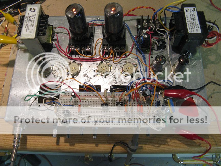
                    • Just finished another amp I was working on and decided to give this one a go again. Chassis is a little rough, did not want to waste any of my other ones and this one is too bad for anything else. I slapped on a Hammond 125E OT as it has multiple impedances, I thought it would go lower, will have to use a 70V transformer. I just set up an input stage and a LTP PI along with the output stage. Start small and add later when this portion is debugged.

                      The power supply consists of a 24V transformer, bridge rectified and ending up with 34V. Would have liked more but using a doubler gets us over 50V. Using 35C5's and a transformer with 35V AC would get 50V, would be worthwhile for anyone so inclined to make a low voltage low wattage amp. I had some 25L6's and the 24V transformer so I went that way. The 35C5 is a lower power tube than the 25L6 but it looks like it might swing more current at lower voltages, is I ever find some cheap I might try it.

                      Other than that the 6AU6's I ran off a 6V supply to make things simple. Four of them in series could be run off the transformer. I was going to drop the cathode follower to keep the design at four preamp tubes. The first stage and PI can easily overdrive the output tube. I did fixed bias on the outputs as I wanted to wring out every microwatt that I could. I just got it running and haven't had much time to see what it can do. I had the primary impedance at 3k, the lowest this transformer has for my 8 ohm speaker. Tomorrow I will try for more power with a lower impedance. As it is the power level would just be good for someone with a 100dB speaker living in an apartment that wants the amp overdriven without bothering the neighbors. I would like to get some cleans at that level.

                      Oh right, the picture.

                      Last edited by printer2; 07-27-2014, 04:44 AM.

                      Comment


                      • Perhaps you can start a new thread?! It's a well liked topic... seem a waste to bury it in this old thread

                        Comment


                        • Not sure how much farther you can take it. I can get it loud enough that I can practice with it fairly clean going into a 98 dB speaker and you would not disturb anyone. Maybe up to 0.1W, not loud enough that you could really distinguish the subtleties in using a tone stack or distortion of one type or another. If I got it up to the 1/2W range then it would be worth playing around with the circuit. With the output stage limiting the power there is not much sense playing around with the rest of the circuit.

                          I'll look at it again in a while, maybe something will dawn on me.

                          Comment


                          • Thought about it, figured that rather than 25V output tubes use a 12V, the 12L6 instead, can also use the 12AU6 or another 12V pentode. Use a 12V transformer, for the high voltage supply and use a voltage trippler getting about 48V. At 48V the above bundle of wires produced a usable volume, maybe a 1W amp. More work to be done but looks a little promising.

                            Comment


                            • Where can I have a look at the schem in a higher resolution ( legible)?


                              The link on the 1st page doesn't work anymore.

                              Comment


                              • Originally posted by Alf View Post
                                Where can I have a look at the schem in a higher resolution ( legible)?


                                The link on the 1st page doesn't work anymore.
                                http://i406.photobucket.com/albums/p...psa539c642.jpg

                                Best I have right now. Schematic seems to come up from the new thread I started.

                                http://music-electronics-forum.com/t37180/

                                Comment

                                Working...
                                X