Ad Widget

Collapse

Announcement

Collapse
No announcement yet.

Gibson BR-1 build

Collapse
X
 
  • Filter
  • Time
  • Show
Clear All
new posts

  • Gibson BR-1 build

    Does anyone know the supply voltage might be for the BR-1? I just got a field coil radio and wanted to use some of the parts in making a 40's amp and found a recording of this one I liked. It also helped that I have the preamp tubes already and am thinking of 6K6's for output in place of the 6F6G's in the radio. (Oh no, the low voltage amp got pushed aside for the time being)

    http://www.prowessamplifiers.com/sch...Gibson/br1.pdf

    I am thinking around 250V given that the 6L6G datasheet I have has a 120 ohm resistor for cathode bias at 250V, different datasheet below but with the voltage and current it works out to be the same.

    http://www.r-type.org/pdfs/6l6g.pdf

    Also on the schematic it looks like there is a 1.8k resistor on the 6SJ7 but I may be wrong. If anyone could second guess me it would be appreciated.


    Well went over the other thread here on the BR-1 and this time clicked on the other schematic listed, much better resolution so I have my resistor value.

    http://music-electronics-forum.com/t14128/
    Last edited by printer2; 09-30-2012, 05:54 PM.

  • #2
    FWIW two older Gibson amps I've ran across have been just under 300Vp. The last one I was inside (sorry, can't remember the model) was 290Vp with modern wall voltages. So about 255Vp back in the day.
    "Take two placebos, works twice as well." Enzo

    "Now get off my lawn with your silicooties and boom-chucka speakers and computers masquerading as amplifiers" Justin Thomas

    "If you're not interested in opinions and the experience of others, why even start a thread?
    You can't just expect consent." Helmholtz

    Comment


    • #3
      Thanks, figured I was in the ballpark but always nice to know I was not out in left field.

      Comment


      • #4
        Printer2,
        I have some notes made when I had a BR-1 on the bench in 1993. Unfortunately, my notes do not verify the line voltage. These day's I always set the power line voltage to 120 VAC when I take readings. I do remember that the amp was pretty much all original when it arrived at the shop including a working field coil speaker.

        Anyway...the voltages I did record were:
        415 V dc at the feed to the field coil
        270 V dc at the OT center tap
        260 V dc at the 6L6 plates
        225 V dc at the the junction of the PI 100k plate resistors
        100 V at the 6SN7 PI plates
        125 V at the 6SC7 plates (i.e. second gain stage tube)
        97 V at the 6SJ7 first pre-amp stage pentode plate

        Hope that info is useful to you.

        Cheers,
        Tom

        Comment


        • #5
          My line voltage is 120V during the day and 125V to 127V evenings and night. I would have done my work during evening hours. So at 120V line and 270 at the OT CT that would be right in line with what I had. Did they use the same PT in ALL those old Gibsons?
          "Take two placebos, works twice as well." Enzo

          "Now get off my lawn with your silicooties and boom-chucka speakers and computers masquerading as amplifiers" Justin Thomas

          "If you're not interested in opinions and the experience of others, why even start a thread?
          You can't just expect consent." Helmholtz

          Comment


          • #6
            Originally posted by Chuck H View Post
            My line voltage is 120V during the day and 125V to 127V evenings and night. I would have done my work during evening hours. So at 120V line and 270 at the OT CT that would be right in line with what I had. Did they use the same PT in ALL those old Gibsons?
            Your readings agree with my experience here Chuck.
            Seems like the voltages we have posted are within expected tolerances.
            I've only seen two BR-1s so I just don't have enough experience with them to know about variances in the PT design or with any other parts used.
            Cheers,
            Tom

            Comment


            • #7
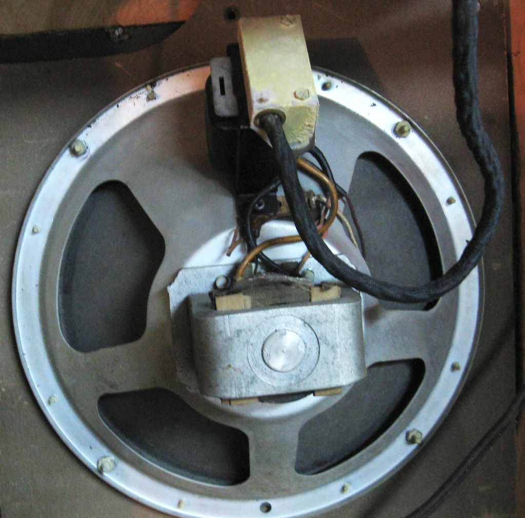
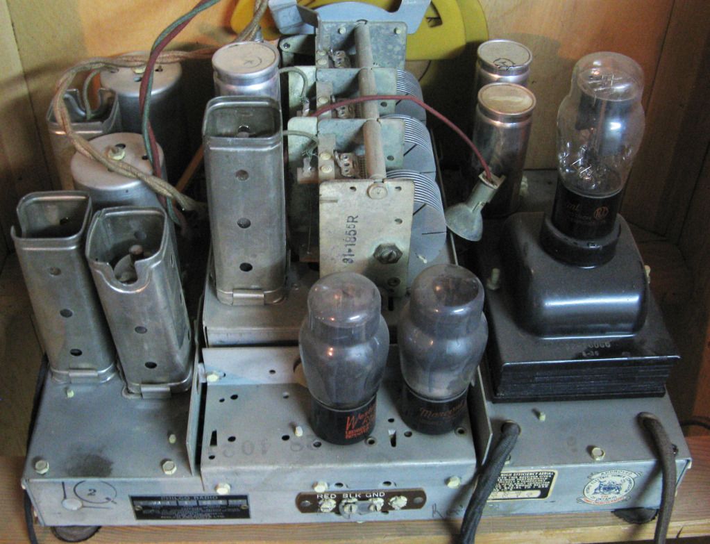
              You guys are amazing. Tom, more than I could have hoped for. I probably should put this in the conversion forum but here is some pictures of a Philco radio I want to run 6K6's rather than the 6F56G's in it now. Otherwise I want to use the BR-1 circuit.


              Comment


              • #8
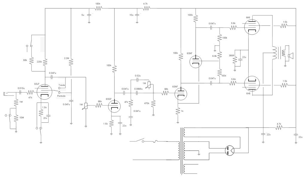
                I kind of know how it is my mother can not follow a recipe 100%. So I took the BR-1 schematic changed the output tube, and added a four pole switch to go from the pentode preamp of the amp to running it in triode but in grid leak. The screen resistor on the pentode is 470k rather than the schematic value, cut and paste is great but remember to change the values. Looking for other opinions, was debating doing a morph control on the pentode but the grid leak is more traditional, not that I am much of one for tradition anyway.

                Comment


                • #9
                  Isn't the 10M grid leak way above the spec, and shouldn't it be after the cap?

                  Jaz

                  Comment


                  • #10
                    Oops, done late last night, when I cut and pasted to include the grid leak I put it on the wrong side. The 10M grid leak value I took from the Gibson GA-20. I thought they were anywhere between 3 and 10 Meg, I have no experience with them it so am easily persuaded.

                    Comment


                    • #11
                      The important thing is that the 10M resistor and switching circuit needs to be on the grid side of the input cap. Otherwise the grid of the input tube has no 0V reference and can "run away" by drawing excessive current.
                      "Take two placebos, works twice as well." Enzo

                      "Now get off my lawn with your silicooties and boom-chucka speakers and computers masquerading as amplifiers" Justin Thomas

                      "If you're not interested in opinions and the experience of others, why even start a thread?
                      You can't just expect consent." Helmholtz

                      Comment


                      • #12
                        Just was sloppy and not paying attention. Not sure if I will bother with grid bias or not yet as I do not know if it will change the sound of the amp much.

                        Comment

                        Working...
                        X