Announcement

Collapse
No announcement yet.

I have a long question about my P-P builds gain.

Collapse
X
 
  • Filter
  • Time
  • Show
Clear All
new posts

  • I have a long question about my P-P builds gain.

    here is the schematic.


    I was playing the amp the other day and using my strats with standard PU's past 4 it begins to break up and the breakup is not smooth. I usually play it below 4 . If you look at the schem is what I built basically a 5E3 with larger tranny's because I have a higher voltage than a stock 5E3 . I was looking for headroom and up to 4 on the vol it is clean and pretty loud and I can live with that. However I did add a switch stdt to switch out the 25uf second gain bypass cap and add in a 112K NFB loop like an 6G2 brown princeton only double the resistance just so I did not get quite as much NFB and it also has a adj/fixed bias and the tone stack is the same as the 6G2 .

    So would you say I basically built a high voltage 5E3 with one vol and one tone and two inputs . I just use one triode of the 12ay7 preamp . I did wire it at first like the 5E3 tone stack but it broke up far to soon so I changed the wiring like the 6G2 and it did not break up nearly as soon. Don't know exactly why but it did change the amp it was not acting like a 5E3 anymore.

    I built it using larger tranny's the OT is twice the size as a BF deluxe and the PT has 325-0-325 @150mA .

    I added the switch so it would be more like an 6G2 with no bypass cap and a NFB loop so if I switch this in to get the same vol as with the bypass cap and no NFB I need to turn the vol up 2 numbers .

    My goal was clean headroom with good bottom end . It does not lose the bottom end switched to NFB mode it's just tighter. On 4 it is pretty loud and with the NFB no bypass it does break up but a lot later on but the sound is not quite the same thing , it's tight and loses overtones. I wanted to add a switch just to cut out the second gain bypass cap and not add the NFB but I like both options. I used the same switch fender used for the ground switch and that's all that will fit in this build.

    So what can I do to get more headroom past 4 without the NFB loop and the bypass cap in play because it sounds best set that way. I don't want to lose the bottom end .

    Can I use a 12at7 instead of the 12ax7 for the second gain and PI or if I use the other triode of V1 12ay7 and wire one input to the unused triode without a bypass cap to drop the gain and if I do that I need to change the input resisters to 33K ohm instead of 68K ohm, can I just leave the one vol pot if I do this and leave the 1 meg resister to ground as is ? I don't have room for another vol pot so say if jumper the grid pin on the 12ay7 and say plug into the input with no bypass cap will the triode that has the bypass cap being not plugged into go to ground through the 1 meg and the one vol pot will work with either triode or do i need a dual gang vol pot?

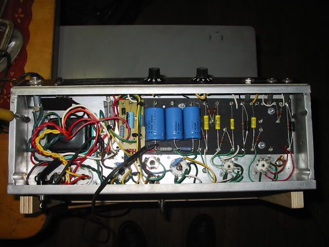
    I know this is asking a lot but it's just a thought . I don't need a high and low input set. I don't have any room to add more switches and if I tried they would be on the back of the chassis real close to the preamp tube V1 and second gain and PI V2 so doing that I may create some noise . here is a photo of the chassis inside.

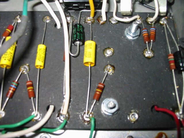
    this is the area the switch fit in

  • #2
    Well... First things first. If headroom is the goal then you need to monitor signal integrity. If any of the stages are giving you asymmetric distortions or breaking up prior to the power tubes these things need to be dealt with first. The easiest way (and the only way I know) is with a scope. Got one? Or can you access one? It would be a pretty easy tweak once you can see what the wave form is doing at each stage.
    "Take two placebos, works twice as well." Enzo

    "Now get off my lawn with your silicooties and boom-chucka speakers and computers masquerading as amplifiers" Justin Thomas

    "If you're not interested in opinions and the experience of others, why even start a thread?
    You can't just expect consent." Helmholtz

    Comment


    • #3
      Originally posted by Chuck H View Post
      Well... First things first. If headroom is the goal then you need to monitor signal integrity. If any of the stages are giving you asymmetric distortions or breaking up prior to the power tubes these things need to be dealt with first. The easiest way (and the only way I know) is with a scope. Got one? Or can you access one? It would be a pretty easy tweak once you can see what the wave form is doing at each stage.
      No I don't have access to a scope . I know this doesn't help but from the schematic am I still close to a 5E3 because if I am then that's what I want to get away from.

      I have never played through a 5E3 or a brown princeton . So I have no idea what they sound like . This is the only amp I ever had with a split load PI . It did sound closer to what I wanted when I had 6L6's in it instead of 6V6's and ran 2 twelves rated at say 50 watts each.

      It's not like the amp does not sound good now but when it does break up it's not as smooth as I would like it to be and it may be the speaker that does this it's just a single weber sig 12 S alnico . I never really pushed the amp hard before this so I can't say how it sounded cranked before. I have nothing to compare it to. 4 on the vol is plenty loud in this apt . All I do know is when I changed ot to a BF tone stack I didn't like it much even with the 6L6's it stripped the sound in my terms sort of sterile. Once you get out of the tween era and into the brown era fenders with the exception of a few odd ones they all had BF tone stacks and LTP PI's . All the amps I've had that were P-P were all LTP like the fender pro jr or the SF bandmaster or even the tweed 1994 Blues deluxe and a crate VC 10 something 15 watt with reverb and a 10 but cathode biased. . Maybe I just don't like the sound of the split phase inverter . I was never a big tweed fan . Even the pignose G40V was a LTP or my 67 super reverb . I don't care about trem or reverb . I had a few a 71 and 77 music master bass amps and they sounded ok but broke up near mid point too. but they had a transformer for a PI . And they were low voltage amps as far as B+. I can crank up my sf champ home brew to 7 before it breaks up and the breakup on it sounds good.
      Last edited by catnine; 01-13-2013, 11:57 PM.

      Comment


      • #4
        The problem you're facing is that you're trying to get a certain sound without having the tools to get there.

        When you say "... it stripped the sound in my terms sort of sterile" that's probably a description of the removal of a form of soft asymmetrical distortion from one stage or another. Since it happened when you changed (?) tone stacks, it is likely that the tone stack lowered the signal down to where you're not getting the softer distortion you like to hear.

        There is a huge amount of misinformation on the net about amp sound and distortion. Much of it is from more-or-less well-intentioned people who stumbled onto something they like, and they then generalize that discovery about one set of conditions as being the answer to all quests for tone. I suspect that people with two discoveries under their belt may begin to believe they have the magic recipe found.

        Worse yet, picking out where something starts to distort by where the volume knob is pointing is really, really misleading. It's trivially easy to make an amp start distorting at any volume setting you like. Just pick a setting you like, then put gain stages in so that one stage starts distorting there. It tells you nothing about what stage is distorting, or how loud the thing gets, or headroom, or the ever-ineffable "tone".

        There's a well-ordered set of conditions to get "high headroom", which is code-words for "biggest swing on the output stage". Once you get to there, you can add gain in front of the output stage and use that gain to create distortion before the output stage if you like. Picking what stage distorts, how much it/they distort with what controls, and what amount of drive is left for the power stage really requires a scope to do in an orderly fashion that could be called "design" instead of "prospecting for nuggets" or "easter-egging". Each of the stages in an amp may distort a different way, and the numbers of their combinations is huge.

        I'm not trying to be snide, that's just the facts. There are many, many ways to get distortion, in most of the stages of even a bog-standard type of tube amp. Picking what kind you want and actually getting it requires either detailed design and simulation as well as iterated build-and-test cycles, or being very lucky because of the large number of variables.

        If you want to do much of this, you really, really need a scope and the skills to use it safely to see what you're doing.
        Amazing!! Who would ever have guessed that someone who villified the evil rich people would begin happily accepting their millions in speaking fees!

        Oh, wait! That sounds familiar, somehow.

        Comment


        • #5
          +++

          catnine, try this, add a 100k resistor between the PI input grid and the 1M dropper. This is supposed to reduce the odd distortions characteristic of cathodyne PI's. You can go a bit higher if you think it made an improvement. If this stops the bad sounding distortion then at least we've eliminated one problem without the need of a scope. But understand that without a scope this is all going to be like shooting in the dark.
          "Take two placebos, works twice as well." Enzo

          "Now get off my lawn with your silicooties and boom-chucka speakers and computers masquerading as amplifiers" Justin Thomas

          "If you're not interested in opinions and the experience of others, why even start a thread?
          You can't just expect consent." Helmholtz

          Comment


          • #6
            Yes RG . I am beginning to see that .especially that part about where the vol pot is set. I started out with a simple build then changed a few things but it does seem like I'm still in 5E3 territory . I thought or at least hoped I would luck out and the amp does sound much better than it did when I started this thing. What I didn't do was add a gain stage after the BF tone stack and that may be all I needed to do to get closer to the sound I needed . I didn't look at the schems close enough to see that . Yet even then the fender SF princeton using the BF tone stack has the same second gain as the 6G2 so I didn't go further. Yet it does have one difference , it keeps the 25uf bypass cap in circuit and uses a smaller value NFB resister and has the 47 ohm to ground after the 1.5K bias resister so it's just like the SF champ it that respect.

            I don't have the option of a scope so I am left with trial and error at this point or just do nothing and ignore the vol setting , it's not like I'm out gigging anymore. It does have voltages close to a SF princeton and I do know the one tone control setup like the 5F2A or 6G2 princeton do create more early breakup than a BF tone stack . If I could come close to the SF princeton then perhaps I would be happy . Seems now the only other option would be to set it up like a BF Deluxe if not the SF princeton .

            Comment


            • #7
              Originally posted by Chuck H View Post
              +++

              catnine, try this, add a 100k resistor between the PI input grid and the 1M dropper. This is supposed to reduce the odd distortions characteristic of cathodyne PI's. You can go a bit higher if you think it made an improvement. If this stops the bad sounding distortion then at least we've eliminated one problem without the need of a scope. But understand that without a scope this is all going to be like shooting in the dark.
              I'll try that . it's easy to do I just place a 100K in series with the 1 meg and pin 7 of the 12ax7.

              Comment


              • #8
                The 100K resistor does not go in series with the 1 M dropper resistor.
                You want to place the 100K from the .02 cap to pin 7, grid.
                (Right now it is probably a wire.)
                Remove the wire & insert the 100K resistor.
                The 1 M resistor will stay attached to the .02 cap.

                Comment


                • #9
                  Right. I wasn't clear. I didn't look at the layout and I didn't want the 100k resistor to be placed behind the 1M load resistor in the circuit. JPB has it right. Place the resistor in line with the lead wire to pin 7.
                  "Take two placebos, works twice as well." Enzo

                  "Now get off my lawn with your silicooties and boom-chucka speakers and computers masquerading as amplifiers" Justin Thomas

                  "If you're not interested in opinions and the experience of others, why even start a thread?
                  You can't just expect consent." Helmholtz

                  Comment


                  • #10
                    Originally posted by Chuck H View Post
                    Right. I wasn't clear. I didn't look at the layout and I didn't want the 100k resistor to be placed behind the 1M load resistor in the circuit. JPB has it right. Place the resistor in line with the lead wire to pin 7.
                    Right now the .02 cap on the layout one end of the .02 cap meets and or attatched to the 1 meg in one eyelet on the eyelet board . what i meant by in series with the 1 meg was to place the 100k from that eyelet to pin 7 which is now a wire . It may not be in series with the .02 cap . I didn't mean I was placing it in series between the 1 meg and 56k. I'm not breaking the .02 cap and 1 meg connection .

                    Comment


                    • #11
                      Originally posted by catnine View Post
                      what i meant by in series with the 1 meg was to place the 100k from that eyelet to pin 7 which is now a wire .
                      Correct. Mount the resistor on the tube socket with very little lead, then twist a loop into the other lead and run your wire to that.
                      "Take two placebos, works twice as well." Enzo

                      "Now get off my lawn with your silicooties and boom-chucka speakers and computers masquerading as amplifiers" Justin Thomas

                      "If you're not interested in opinions and the experience of others, why even start a thread?
                      You can't just expect consent." Helmholtz

                      Comment


                      • #12
                        Originally posted by Chuck H View Post
                        Correct. Mount the resistor on the tube socket with very little lead, then twist a loop into the other lead and run your wire to that.
                        Before I did anything I played the amp again today just to make certain of the sound since I have not played it since last friday.

                        This time I played around with the tone control and if I bring up the treble the breakup is smoother. It still breaks up just past 4 on chords but not so bad with the trebel up more. Then I flipped the switch to take out the 25uf bypass cap and add in the NFB loop and I need to bring the vol up a bit to match the vol without the bypass cap and NFB and if I bring the treble up just a bit more like on 8 it does not break up much at all . I also used the strats tone and this also changes the point of breakup in a different way than the amps tone does.

                        I was in the bedroom and had the door shut and the hallway door shut and my wife came in and asked me to turn it down because it was drowning out the TV in the living room . Maybe I am fixed on the numbers rather than on the actual loudness.

                        Comment


                        • #13
                          If it helps any, I never look at the knob numbers, I just turn them until it sounds the way I want, whatever the numbers turn out to be.
                          Education is what you're left with after you have forgotten what you have learned.

                          Comment


                          • #14
                            Originally posted by catnine View Post
                            Maybe I am fixed on the numbers rather than on the actual loudness.
                            Well you would be in good company!!! I read that Stevie Ray Vaughan's tech use to remove the knobs on Stevies amps and re set them so the end adjustment would match up to where they "should" be!?!

                            And FWIW I also suffer the affliction of no practice space and family close at hand. In fact my wife and I have taken in her parents as they are becoming too frail to care for themselves in all aspects. I've never played my guitar less I think I need to find a local band just so I can play my guitars and amps.

                            There's nothing wrong with your expectations. Your ears will tell you when it's right for YOU. That's how artists find inspiration. Compromise and complacency are always unfortunate. Avoid them at any opportunity.
                            "Take two placebos, works twice as well." Enzo

                            "Now get off my lawn with your silicooties and boom-chucka speakers and computers masquerading as amplifiers" Justin Thomas

                            "If you're not interested in opinions and the experience of others, why even start a thread?
                            You can't just expect consent." Helmholtz

                            Comment


                            • #15
                              Originally posted by Chuck H View Post
                              And FWIW I also suffer the affliction of no practice space and family close at hand. In fact my wife and I have taken in her parents as they are becoming too frail to care for themselves in all aspects. I've never played my guitar less I think I need to find a local band just so I can play my guitars and amps.
                              Tell me about it. I've got an old Ampeg V4 that really needs to be run wide open so I can blow out the carbon from the valves. I think my wife would call 911 on me.

                              Comment

                              Working...
                              X