Announcement

Collapse
No announcement yet.

Range of bias voltages for power tubes in fixed bias?

Collapse
X
 
  • Filter
  • Time
  • Show
Clear All
new posts

  • #46
    Originally posted by Steve Conner View Post
    Wow. That amp has the devil coming out of it! Steve, that build deserves another thread. If you've already got one please point me to it.

    I think MWJB makes some very practical points about retrofitting. Maybe retrofitting to include the bias-box would be too much of a PITB for the average guy, or too invasive a procedure for a vintage amp. But if someone's doing a complete teardown/revision (aka "gutting") an old amp then there's not much impediment to building a circuit around a bias-box. Today's amp market also involves a lot of DIY builders who build clones of classic circuits. In that case the concerns about being too labor intensive or too invasive go away. For a new amp build it would be easy to accommodate the bias-box into the design.

    Looking forward to designing/building new amps: I've seen a lot of amps that have very poorly conceived bias supplies; it seems to me that this occurs because designing bias systems isn't very glamorous, so people don't put a lot of effort into it. It's an afterthought. There's a lot to be said for well thought out systems that are modular and offer turnkey solutions for designers/builders. If you're designing an amp, the ability to buy an off-the-shelf solution for the bias subsystem saves time and effort. If R.G. can come up with an embodiment that provides a complete bias-system in a compact package that's easy to incorporate into an amp design, then it might catch on in the DIY builder's market.

    Unfortunately, I don't think that companies that manufacture amps would have much interest in it -- they tend to prefer using other peoples' IP without paying for it.

    As far as personal applications go, I've told R.G. that if he had something up and running right now that would work in my application, I'd definitely try it out. For my application, I'd need some mechanism that would allow me to configure the LED set point, rather than being blind to what the green light actually means. I think DIP switches could serve that purpose.
    "Stand back, I'm holding a calculator." - chinrest

    "I happen to have an original 1955 Stratocaster! The neck and body have been replaced with top quality Warmoth parts, I upgraded the hardware and put in custom, hand wound pickups. It's fabulous. There's nothing like that vintage tone or owning an original." - Chuck H

    Comment


    • #47
      Originally posted by Steve Conner View Post
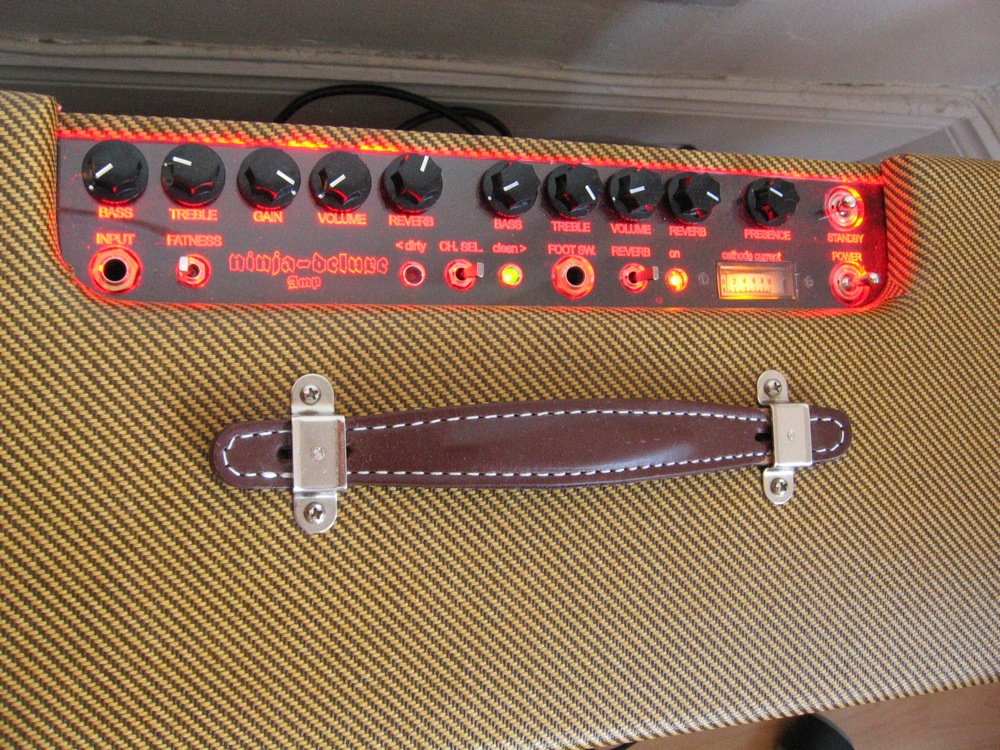
      I remember seeing one of Weber's higher powered amp kits with a bias probe built in. The rear panel had a bunch of bias pots, a digital panel meter, and a selector switch to read the cathode current of each tube. I thought that was a good idea.
      I have this on my three builds, this is the Hiwatt DR201 build:

      Attached Files

      Comment


      • #48
        bb5000, that's the amp I remember! Sorry if I confused your build with a Weber kit. Do you have a schematic of the bias circuit? I think it would be relevant to this thread.

        Bob P, I never did a formal build thread for it. There's a brief summary of the build on my blog, if you go to scopeboy.com/amps and click on Ninja Deluxe. No schematics, all I have are some ratty hand-drawn ones that I never got round to redrawing.
        "Enzo, I see that you replied parasitic oscillations. Is that a hypothesis? Or is that your amazing metal band I should check out?"

        Comment


        • #49
          There is always one other consideration:
          - Do you want guitarists messing with amp bias anyway? Idiot proofing is always the bane of a design engineer. The more "bells and whistles" you add to more things that can go wrong.

          You run into conflicting arguments here
          The Keep It Simple Stupid (KISS)
          vs add a PIC (or similar) micro that does it all without player intervention.

          Just spent a whole day in the day job fixing a problem with a Laser Drive electronics box. It had a fault in the fault detection circuitry which was shutting it down when there actually was no fault. Did'nt even have the satisfaction of venting at the design idiot since in this case that was me.

          It is easy to get to clever for your own good.

          Cheers,
          Ian

          Comment


          • #50
            HOLY COW. I thought myself a vintage Fender enthusiast. I have never come across a SUPER TWIN REVERB!! Holy cow!!
            Is that a 2x12" combo amp or a head? What speakers were packaged with it to handle 6x6L6 output.
            Super cool.

            Comment


            • #51
              I did a restore of one - It is a 2 x 12" Combo.
              It put out a measured 175 W RMS continuous sine wave into a 4 Ohm dummy load.

              Sold it to my apprentice for the Aus$300 that I paid for it not working + a nominal $100 for the restoration parts.

              He lent it to his brother who played bass through it with the volume knob on 10. It set fire to the the wire flex leads which go from the speaker terminal to the voice coil connections on the cone (yes real flames, actual fire).

              2 replacement speakers later (they were in parallel so once the first burned out the lead the second tried to handle all the power and quickly went out in sympathy) it just fired up again. No damage to the amp itself. It just about bullet proof.

              The speakers were just the standard Fender 12" 100W replacements that would normally go in a 100W Twin Reverb. They were probably under rated for this amp. Told him not to let his brother play bass through it again, at least not with the knob on 10.

              He claimed that when playing guitar through it it with his band, it blew away a double Marshall stack for stage volume. A forklift is recommended to carry the damn thing.

              Cheers,
              Ian

              Comment


              • #52
                Originally posted by Gingertube View Post
                It had a fault in the fault detection circuitry...Ian
                Priceless I'll stick with KISS

                Comment


                • #53
                  Ian, that's a great story!

                  Originally posted by timrichter9 View Post
                  HOLY COW. I thought myself a vintage Fender enthusiast. I have never come across a SUPER TWIN REVERB!! Holy cow!!
                  Is that a 2x12" combo amp or a head? What speakers were packaged with it to handle 6x6L6 output.
                  Super cool.
                  Here's the description of the Super Twin Reverb in the Fender Field Guide.

                  Mine still has the original Fender blue-label speakers. I seem to remember that when I looked up the EIA speaker codes the manufacturer was Pyle. That surprised me.
                  "Stand back, I'm holding a calculator." - chinrest

                  "I happen to have an original 1955 Stratocaster! The neck and body have been replaced with top quality Warmoth parts, I upgraded the hardware and put in custom, hand wound pickups. It's fabulous. There's nothing like that vintage tone or owning an original." - Chuck H

                  Comment


                  • #54
                    I would say to use some 21st century technology and will vote for a uCU bias adjustment unit. Here's how I see it:

                    1/ One pot on the back panel to set how hot the tubes will run. For example a 20-80% range.
                    2/ A 3 position slide switch to select between EL34, 6L6 and KT88/6550 tube types.
                    Everything else like when and how many times the bias will be adjusted, when a tube will be considered bad etc can be incorporated in the software.
                    If you like even a small LCD display can be added.

                    Comment


                    • #55
                      On the subject of using 21st Century Technology and a uC, I can think of an enhancement to R.G.'s proposed device that we haven't talked about yet, and it only involves 20th Century Technology. Think of it as Part 5 of the ways to Immortalize your amp.

                      If you're going to use a uC to measure voltage drops across current-sensing cathode resistors, then you should do something more useful with the information than to just trigger Green and Red LEDs to help someone adjust the bias point. I think that you should use the uC to monitor bias current at all times, so that if a bias failure is detected, it shuts off the mains supply to the amp. This wouldn't be too hard to implement with comparators and a relay. It's such an obvious thing to do that I'm willing to bet that somebody probably has a patent on this idea.
                      "Stand back, I'm holding a calculator." - chinrest

                      "I happen to have an original 1955 Stratocaster! The neck and body have been replaced with top quality Warmoth parts, I upgraded the hardware and put in custom, hand wound pickups. It's fabulous. There's nothing like that vintage tone or owning an original." - Chuck H

                      Comment


                      • #56
                        Actually, I did a version of that with comparators and MML (Mickey-Mouse Logic) some years back.

                        Instead of looking for bias failure, it looked at time-averaged cathode current on an individual tube, and when any tube went over X current averaged over Y time, it turned off the tube. This particular version used a MOSFET in the cathodes of each tube, but it's also reasonably easy to turn off a MOSFET in the high side of the B+, or to turn off the AC power to the primary of the power transformer.

                        It had a number of possible inputs if you wanted to sense other things. This could include
                        - loss of raw bias voltage, or just below some threshold
                        - thermistors sensing something overtemp; you could put one on the PT, one on the OT, one loose in the cabinet air, etc.

                        Also offered both latched off till power cycled and a reset switch, and lit a light for which tube(s) went over.

                        This was my pre-uC days, so it took several ICs to do. Today, you'd have comparators and one uC. Well, I would anyway. I've put in the time to get over the hump of programming a uC in ones for my fun and amusement, so I can dream up some logic thing like "Look at the input comparators and thermistors; if it's too hot, do this; if that's OK, look at the currents and do *this*."

                        I think I posted some description of it either here or at the precursor ampage site back in the day. Got a lot of "that's too complicated, won't work, won't work right, users don't want that, too much, too many, too soon, silly, overblown, yada, yada, yada". Much the same vein as the comments on individual bias pots per tube and assistance lights to quickly set them to some predetermined bias point.

                        I probably still have the design files somewhere.
                        Amazing!! Who would ever have guessed that someone who villified the evil rich people would begin happily accepting their millions in speaking fees!

                        Oh, wait! That sounds familiar, somehow.

                        Comment


                        • #57
                          Originally posted by R.G. View Post
                          I think I posted some description of it either here or at the precursor ampage site back in the day. Got a lot of "that's too complicated, won't work, won't work right, users don't want that, too much, too many, too soon, silly, overblown, yada, yada, yada". Much the same vein as the comments on individual bias pots per tube and assistance lights to quickly set them to some predetermined bias point.
                          It doesn't surprise me that some DIY-types who are learning to solder-up a tube amp kit wouldn't want a circuit that's too complicated for them to understand. Lots of them are treading water to just to finish building a tube amp, and many of them have been brainwashed to think that solid-state is the work of the devil. As devices go, a uC takes the problem one step further along the "hard to understand" spectrum, because if you don't release your code then people are forced to looking at your uC as a black box that performs black magic. Not that that is necessarily all bad ...

                          But saving a malfunctioning amp from certain disaster by preventing it's self-destruction? Those kinds of protection circuits are EXACTLY the kinds of things that I'd WANT in a modern tube amplifier, and they're EXACTLY the kind of things that some companies (loud) are building into some of their current products. I don't think that there's anything WRONG in using modern electronics to save tube amplifiers from certain self destruction when a critical part fails. In contrast, I think that's exactly the RIGHT thing to do. Taking a look at an SVT Classic schematic changed my mind about what some of the current manufacturers are doing right now. It looks like their products may be designed better than they were in the golden era. For example, the SVT Classic uses comparators to track bias currents, and if a critical failure is detected then the amp is shut down and the green power LED changes to blinking red. To me, that option of a soft shutdown is a lot better than frying a lot of expensive parts.

                          I'll say it again -- if you had a uC box ready to go right now that offered 6-way bias and a fail-safe circuit to shut things down when I'm about to blow out a sextet of tubes, or worse yet, fry the OT, then I'd be watching tracking information right now instead of typing this post.

                          BTW, did you get my recent email about Neutron optos? It should provide a good test of how good your archiving / retrieval system really is...
                          "Stand back, I'm holding a calculator." - chinrest

                          "I happen to have an original 1955 Stratocaster! The neck and body have been replaced with top quality Warmoth parts, I upgraded the hardware and put in custom, hand wound pickups. It's fabulous. There's nothing like that vintage tone or owning an original." - Chuck H

                          Comment


                          • #58
                            I don't see the automatic biasing thing being huge problem with microcontrollers, but rather the gamut of ways to display this information to the user and what current to set the bias in the first place (via input from the user). If you include an LCD, you've also got to think of the poor end user trying to figure out how to mount the thing as well (I've had to cut a rectangular hole in 3mm aluminium to fit a 4 inch LCD and it wasn't a pleasant experience!).

                            If I were to design such a system, I'd probably include a main board with one off board mounted encoder (to adjust bias), a small 2x16 LCD and one or maybe 2 buttons at the rear panel to perform arbitrary GUI functions. The main board would include an MCU of some sort with built in ADC's (probably an ARM M3 - you can get them for under 3 dollars in single quantities with 8k of RAM, which is plenty for FFT's and other stuff), some op-amps for level conversion/measurement and a few pass transistors for bias voltage regulation. Obviously, this is an oversimplification, but it should certainly be possible to get the BOM under 10 dollars, excluding the PCB and whatever you want to use to interface to the user.

                            Other things to think about are the power supply for the MCU and op-amps - where would you 'steal' it from, from an existing power transformer? (I personally use DC heaters so the heater tap is a no brainer for me). What about protection from inadvertent faults?

                            Comment


                            • #59
                              Originally posted by exclamationmark View Post
                              I don't see the automatic biasing thing being huge problem with microcontrollers, but rather the gamut of ways to display this information to the user and what current to set the bias in the first place (via input from the user). If you include an LCD, you've also got to think of the poor end user trying to figure out how to mount the thing as well (I've had to cut a rectangular hole in 3mm aluminium to fit a 4 inch LCD and it wasn't a pleasant experience!).
                              Huge? No.

                              The issues with displays and human factors are in fact what I see as the issue. It is much faster and easier for a human to get a blinky light to turn on or off than to read and interpret numbers, whether the numbers are on a meter, an LCD, computer screen, whatever. Interpreting numbers for your pet amplifier is something to do when it's quiet and you're not going to be disturbed by the audience throwing bottles and the club manager deciding to deduct from your payment for "down time".

                              The red-green light system turned out to be remarkably easy for real humans to use.

                              And mounting it is an issue. I really like the one-LED-per-tube setup with blue=too cold, green-OK, red=too hot. It is really quick and easy to do a bias with this kind of indicator while twiddling a screwdriver. My personal amp has this system in it, and so do the amps in the whole production run of the Workhorse amps. I don't remember even one question about how to do the biasing on the amps, even with questions about everything else. One LED per tube is quite a small area of control panel.

                              I would NOT put this on the front/top surface of the amp. I'd put it someplace where you have to want to look at it, but not hidden behind a tools-required cover.

                              If I were to design such a system, I'd probably include a main board with one off board mounted encoder (to adjust bias), a small 2x16 LCD and one or maybe 2 buttons at the rear panel to perform arbitrary GUI functions. The main board would include an MCU of some sort with built in ADC's (probably an ARM M3 - you can get them for under 3 dollars in single quantities with 8k of RAM, which is plenty for FFT's and other stuff), some op-amps for level conversion/measurement and a few pass transistors for bias voltage regulation. Obviously, this is an oversimplification, but it should certainly be possible to get the BOM under 10 dollars, excluding the PCB and whatever you want to use to interface to the user.
                              As I said, I'd skip the GUI. The required uC can be under $1.50 in ones.
                              Other things to think about are the power supply for the MCU and op-amps - where would you 'steal' it from, from an existing power transformer? (I personally use DC heaters so the heater tap is a no brainer for me).
                              I just posted a way to get this from the heater supply with a 6V:6V transformer setup to make an isolated 1-2W of DC in another thread.

                              What about protection from inadvertent faults?
                              Kind of like learning to brush your teeth and take showers. A "designer" who doesn't do this kind of thing automatically as part of a design... well, I'd not call them a "designer", not to put too fine a point on it.

                              Of course you protect it from all forseeable faults. Not doing so is naive. Simple to do if you take the time to think about likely failures and human-operator failures, as well as some though about failing safe or at least non-disastrous.
                              Amazing!! Who would ever have guessed that someone who villified the evil rich people would begin happily accepting their millions in speaking fees!

                              Oh, wait! That sounds familiar, somehow.

                              Comment


                              • #60
                                All fail safe procedures mentioned so far can be easily implemented with a uCU so I would vote for it one more time

                                Comment

                                Working...
                                X