Ad Widget

Collapse

Announcement

Collapse
No announcement yet.

Questions about Champion 30 SS amp

Collapse
X
 
  • Filter
  • Time
  • Show
Clear All
new posts

  • Questions about Champion 30 SS amp

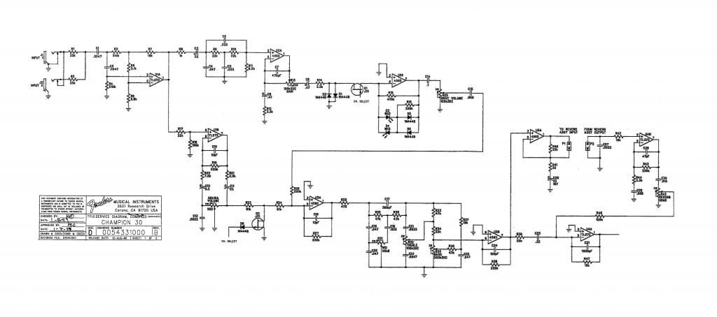
    I have some questions about the design of the clean channel which is extremely bright. I was hoping that someone might be able to explain the "ladder" arrangement for U1B. I was told earlier that C13 (.0022uF) was like a bright cap on a tube amp as it is removed from the circuit as you turn the Normal volume up. After some experimentation I replaced that with a 1000pF cap in series with a 1K6 resistor (along with many other changes) but the clean channel is still brighter than I'd like.

    I have a hunch that R20(7K5) and C12(2.2uF) might set the overall brightness of the clean channel, especially as you turn the Normal volume control up. Any thoughts on that?

    The full preamp:


    The same but cropped:
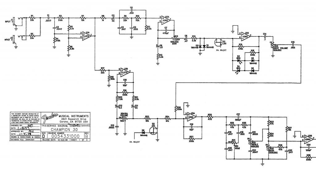


    I have 3 of these amps that I am experimenting with. I have the first one sounding really nice on both channels, although I usually keep the Treble at 1 and the Mid at 10. #3 is still stock so I can experiment with R20 and C12.

    Thanks!

    Steve Ahola

    P.S. I have questions about the tone stack, too, but will ask them later.

    Click image for larger version

Name:	FenderChampion30schempreamp2_zpse5f10228.jpg
Views:	1
Size:	43.6 KB
ID:	867432

    Click image for larger version

Name:	FenderChampion30schempreamp2crop_zps8c513da1.jpg
Views:	1
Size:	61.1 KB
ID:	867433
    The Blue Guitar
    www.blueguitar.org
    Some recordings:
    https://soundcloud.com/sssteeve/sets...e-blue-guitar/
    .

  • #2
    Steve - R20, C12 roll off too low to make it your problem. My money is on the tone stack. You might try putting some tones or a slow sweep into the amp (using Audacity) and measuring the signals at each op amp output. I'll bet you see a low-cut/high-boost after the stack.

    If you want to tweak the stack, you can try increasing C17, C22, and/or decreasing C21, C23. Any/all of those changes should move the response in your direction (more bass, less treble).
    “If you have integrity, nothing else matters. If you don't have integrity, nothing else matters.”
    -Alan K. Simpson, U.S. Senator, Wyoming, 1979-97

    Hofstadter's Law: It always takes longer than you expect, even when you take into account Hofstadter's Law.

    https://sites.google.com/site/stringsandfrets/

    Comment


    • #3
      Originally posted by uneumann View Post
      Steve - R20, C12 roll off too low to make it your problem.
      So what is the roll-off? I assume that the caps on the right side of the "ladder" (the output) will roll off the highs and that the caps on the left side (the inverting input) will boost the highs.

      My money is on the tone stack.
      The tone stack works fairly well with the Drive channel after I did some mods to it. (I need to write up the mods I've done to #1 so far and will post it here. Other than having to keep the treble around 1 and the midrange around 10 I am very happy with how it sounds with both channels.)

      You might try putting some tones or a slow sweep into the amp (using Audacity) and measuring the signals at each op amp output. I'll bet you see a low-cut/high-boost after the stack.
      I will give that a shot. BTW the amp has plenty of bass, sometimes too much for the stock speaker. I replaced the .33uF coupling cap C25 with a .22uF cap connected to a center off SPDT toggle switch to add in a .047uF or .1uF cap.
      So how would I boost the mids a little bit? I am very baffled by the midrange section of the stack.

      If you want to tweak the stack, you can try increasing C17, C22, and/or decreasing C21, C23. Any/all of those changes should move the response in your direction (more bass, less treble).
      I did experiment with different cap values in the tone stack but went back to original values except for replacing the 560pF C17 with a 1000pF cap. I thought that increasing C21 would make the trebles less bright- do I have that backwards? I also thought that increasing C23 (0.047uF) would boost the bass.

      Fender modified that tone stack in some of the newer models, basically tapping the bass pot feed off the output of the preceding op amp (U3A on the Champion 30, U3B on the FM212R.) Here is the tone stack from the FM212R schematic.


      Thanks for your help! I'm still trying to wrap my head around ss circuits and differential op amps.

      Steve Ahola
      Attached Files
      Last edited by Steve A.; 06-15-2013, 06:55 AM.
      The Blue Guitar
      www.blueguitar.org
      Some recordings:
      https://soundcloud.com/sssteeve/sets...e-blue-guitar/
      .

      Comment


      • #4
        So what is the roll-off? I assume that the caps on the right side of the "ladder" (the output) will roll off the highs and that the caps on the left side (the inverting input) will boost the highs.
        Yes, that can be true, but what a cap on either side does also depends on what it's connected to.

        Look at the left side. Assume the vol is up full so the bottom of C12 is grounded. At high freq's C12 is a short, so the gain of U1B is ~R19/R20. At low freq's C12 will have a reactance (resistance). When C12 looks like R20 their combined resistance doubles, and thereby halves the gain. That's the -6db point. So compute F = 1/(2piRC).
        C=2.2uf, R=7.5k. I get 9.6 hz. At lower pot settings (say 1/2 volume), the -6db point will drop even lower since the pot resistance (25K) to ground is added to R20, shifting the Freq roll-off even lower.

        On the right side, the C11 cap is really just a coupling cap that feeds the next stage (U3a). It blocks DC, but is big enough to pass everything of interest.
        “If you have integrity, nothing else matters. If you don't have integrity, nothing else matters.”
        -Alan K. Simpson, U.S. Senator, Wyoming, 1979-97

        Hofstadter's Law: It always takes longer than you expect, even when you take into account Hofstadter's Law.

        https://sites.google.com/site/stringsandfrets/

        Comment


        • #5
          Originally posted by uneumann View Post
          On the right side, the C11 cap is really just a coupling cap that feeds the next stage (U3a). It blocks DC, but is big enough to pass everything of interest.
          I didn't notice that because of the way it was drawn to accommodate the volume control in the feedback loop- D'oh!

          An RC network to ground on the inverting input of an op amp will increase the high frequencies not reduce them as it would if it was connected to the non-inverting input- right?

          Thanks!

          Steve
          The Blue Guitar
          www.blueguitar.org
          Some recordings:
          https://soundcloud.com/sssteeve/sets...e-blue-guitar/
          .

          Comment


          • #6
            An RC network to ground on the inverting input of an op amp will increase the high frequencies not reduce them as it would if it was connected to the non-inverting input- right?
            Such "rules" are fraught with peril since there are many other variables that can impact what a cap will do. Its best to try to understand what's going on in the circuit. Take the classic "follower" opamp circuit (U1B or U2B) with signal going to the + input. Normally, you feed some of the output back to the neg-input through a resistor/capacitor network. The output is going to swing as hard as it has to to make the neg-input voltage follow the + input. If you diminish the HF signal due to a cap anywhere along that FB network (at the output or the neg input), the opamp has to "work harder" to get the neg-input to match the voltage you're putting on the + pin.

            If the cap is on the output (to ground), you're simply loading the output more - meaning the amp has to provide more current to get the needed voltage swing. That said, you will not see any change to the output voltage as long as the current can be provided by the amp. As you increase the cap value, you will eventually exceed the current that the output can provide and you'll see clipping or some other distortion that reduces the output voltage.

            If the cap is on the neg-input side (to ground). Its impact depends on the presence of a feedback resistor network. Usually you'll have a network like the ones shown for U1B or U2B. The resistors determine stage gain since the output has to swing far enough to make the neg-input voltage the same as the pos input. If you add a cap to the neg-input, it's like reducing the resistor to ground on the neg-input side of the network, and that causes the output to swing even farther (more gain) to get the needed voltage at the neg input. So, yes, a cap to ground in that case will cause more HF gain.

            If the cap is part of the feedback network from output to neg-input like C10, then it reduces the effective feedback resistance (otherwise set by R19). A reduced feedback resistance means the opamp doesn't have to swing so far to get the right voltage on the neg-input - so you get reduced gain. A cap in that position reduces HF gain.

            Hope that makes sense...
            “If you have integrity, nothing else matters. If you don't have integrity, nothing else matters.”
            -Alan K. Simpson, U.S. Senator, Wyoming, 1979-97

            Hofstadter's Law: It always takes longer than you expect, even when you take into account Hofstadter's Law.

            https://sites.google.com/site/stringsandfrets/

            Comment


            • #7
              Originally posted by uneumann View Post
              Hope that makes sense...
              Thanks! I was referring to a simple op amp circuit that would normally have just a resistor and sometimes a cap in the feedback circuit- like many of the ones in this schematic. Can you explain what is going on with U2B in the Drive channel, with the two resistors, two LED's and two diodes? I got a headache just thinking about that one. After experimenting a bit I ended up replacing the 470k resistor R15 with a 270k resistor in parallel with a 100pF ceramic cap which smoothed out the sound a bit, getting away from the stock "buzz saw" voicing of the Drive channel. However I was wondering how those diodes and LEDs affected the circuit...

              Steve
              The Blue Guitar
              www.blueguitar.org
              Some recordings:
              https://soundcloud.com/sssteeve/sets...e-blue-guitar/
              .

              Comment


              • #8
                I just noticed that there are no coupling caps between the 3 op amp stages for the Normal channel. So I guess that unlike tubes there is no DC voltage on the op amp output that needs to be blocked- is that correct? The OD channel has coupling caps between all of its stages but I guess that is to cut the low frequencies.

                I noticed that the Champion 30 has a .047uF cap going from the CW terminal of the mid control to ground, a cap that is not in the FM212R schematic. With the mid control set to 10 there would be no difference but how does would cap affect the other settings in theory?


                Steve Ahola
                The Blue Guitar
                www.blueguitar.org
                Some recordings:
                https://soundcloud.com/sssteeve/sets...e-blue-guitar/
                .

                Comment

                Working...
                X