Ad Widget

Collapse

Announcement

Collapse
No announcement yet.

Removal of one side of the output section and OT ramifications

Collapse
X
 
  • Filter
  • Time
  • Show
Clear All
new posts

  • Removal of one side of the output section and OT ramifications

    Hello everybody,

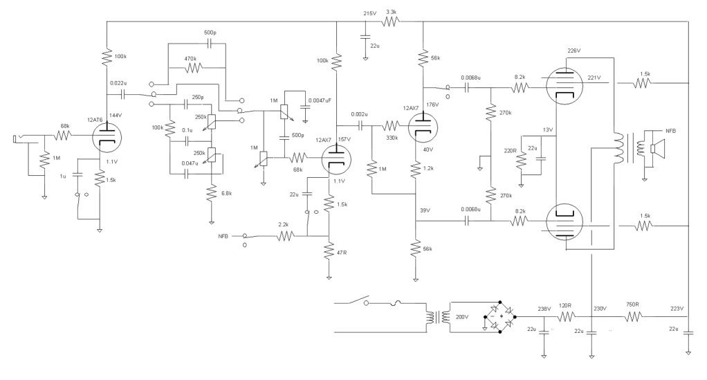
    I have a self-made 4 x KT88 amp with a long-tail pair phase inverter, and I've been experimenting with only using half of the output valves. And by half I mean either one side of the wave-form, or the other side. I stumbled across the idea of amplifying only half of the wave-form when I noticed that one day my amp sounded unusually awesome--it turned out that one of the KT-88's had valves had failed. So then I experimented with removing out put valves and noting the results. The guitar signal going into the phase inverter is realatively asmytricaly clipped, and I find that that the amp sounds best when the output valves are removed in a manner that causes an exaserbation of the asymetrical clipping.


    Am I right in thinking that by removing one half (one side) of the output valves, the result is that effectively the removed side behaves as though it is in cutoff, and that therefore only 1/2 of the output transformer is used?

    If so, is there a way to wire a push-pull output transformer so that all four kt-88's can be wired in parallel without smoking the OT? The Kt'88s will be biased way cold, and so will be in cutoff much of the time.


    Funny thing is that I used to be so picky about biasing the output valves preciesly, making sure everything is 'balanced' and hi-fi as much as possible in the output stage. So much for that... the non-balanced output section makes for awesome overdriven sounds even at low volume!

    Cheers,
    A
  • #2
    By removing 1/2 of the output tubes (one side) you are basically running the amp 'single ended'.
    What that is going to do in the long run to the OPT I have not a clue.
    Core saturation is a concern.
    I think if you parallel four tubes in this manner you will run into transformer dissipation rating problems.

    Comment


    • #3
      If you prefer the sound of the amp in SE mode, then you should build one, the prolong use of the PP amp with one tube removed will saturate the core and damage the transformer. Alternatively, you can leave both tubes in and turn off the input to one of the tubes.

      Comment


      • #4
        Turning off the signal to the output tubes on one side is a good idea - in fact, I think it's patented. Not that the patent is worth much. But there was an amp company advertising this at one time in the past decade IIRC.

        What you've heard is basically correct. It amounts to setting up the output transformer in single ended mode, but with really small bias for an SE amp.

        You could get into saturation with the transformer. But this would not all by itself be disastrous, because saturation only means that the primary can no longer increase the magnetization in the core to oppose increases in the input volt-time, so the M-field no longer limits current through the primary. Since the current in the primary can't get any bigger than the functioning tube will let it, this is no necessarily an instant disaster, although it may contribute to overheating. This is a different situation than saturating the input of a power transformer with a too-high line voltage and no effective current limit.

        If you think about this, it makes sense because amps have been losing one side of a push-pull stage for almost a century without killing their output transformers. Probably not good long term, but not an instant disaster.

        Transformers die from overheating (and rarely, voltage or mechanical punch-through) of the internal insulation.

        Removing the output tubes from one side of a push-pull offsets the transformer M-field from nearly zero as set by the equal-but-opposite pulls of the currents in the output tubes. Removing the signal from one side of the push-pull leaves the M-field mostly balanced, which is nice because it still cancels B+ ripple noise. You still get asymmetrical clipping, as the remaining stage clips when driven off.

        It is unlikely that transformer saturation distortion ever happens in real life the way that most people think it does. Saturation is a phenomena of bass frequencies. When you feed too many volt*seconds into a winding in one direction, you can get into saturation. DC does this nicely because the seconds are unlimited. But audio has a hard time because it naturally alternates. To get lots of volt-seconds in one direction, you need lots of time, and that means bass. The saturation resistance of a transformer doubles every time frequency doubles. If you can supply 10W at 20Hz without saturating, you can supply 20W at 40Hz, 40W at 80Hz, and 1000W at 2kHz without saturation. There may be other issues, but the saturation side of things goes away very quickly as frequency increases.

        You can tell if your transformer's getting too hot by touching it. Too hot to keep your finger on means you need to start worrying a bit. It may take an hour or two to heat up; there's lots of mass there.

        Note that pulling the input to one of the push-pull sides still offsets the transformer M-field more than just the bias. The unbalanced pulls to one direction of the M-field amount to a DC offset equal to the average of the signal size on that side. It just goes away when the signal quits.
        Amazing!! Who would ever have guessed that someone who villified the evil rich people would begin happily accepting their millions in speaking fees!

        Oh, wait! That sounds familiar, somehow.

        Comment


        • #5
          +1 to all above. And add...

          R.G said:

          Originally posted by R.G. View Post
          Note that pulling the input to one of the push-pull sides still offsets the transformer M-field more than just the bias. The unbalanced pulls to one direction of the M-field amount to a DC offset equal to the average of the signal size on that side. It just goes away when the signal quits.
          I think this translates as, or includes a shift in bias for the remaining operating tubes. The OP mentioned that the tubes will be in cutoff much of the time, but I'm not certain of this. As mentioned, a push/pull amp with the push or pull removed will try it's best to operate in class A. If the amp, operated this way, was actually in cutoff much of the time the wave form would be wildly asymmetrical. Actually clipping off nearly half the output wave form. Now, maybe that's what's happening and you like the tone, but maybe something else is happening is happening as a result of shifted operating parameters. What all this amounts to is that the output may not be in cutoff as much as you think. And therefor the possibility of overheating and damage exists. Also, you should scope the output and identify what's actually going on with the output wave form so that you can attempt to duplicate it in an amp designed for class A operation. Then you can have your cake and eat it too. I wouldn't try running all four power tubes in parallel on a push/pull OT.
          "Take two placebos, works twice as well." Enzo

          "Now get off my lawn with your silicooties and boom-chucka speakers and computers masquerading as amplifiers" Justin Thomas

          "If you're not interested in opinions and the experience of others, why even start a thread?
          You can't just expect consent." Helmholtz

          Comment


          • #6
            Shut off one side of my amp to make a SE. Running Class A but if biased in Class AB you would just get a large second harmonic component if one side of the waveform is severely clipped and the other is clean. I should up the voltage and go to Class AB and do a few more changes, not sure what I want yet.

            Comment


            • #7
              Thanks for all of your posts. As Chuck H mentioned, there's a chance that the sound I like from pulling half of the tubes could be from something other than clipping alone. I'm suspicious that the negative feedback circuit might have something to do with it: as I understand it, the NFB loop will have a lot more work to do, since it's having to correct a tremendously altered waveform and the limit it abilities may be reached sooner. I haven't yet tried comparing conected vs. disconnected NFB.

              I see quite clearly how a PP output stage with one side of the PP section removed behaves similarly to a single-ended amp output stage. But I don't yet see how pulling half the tubes will be different from removing the input signal to half the tubes. In the case of removing the tubes, the center tap will be at B+, the tap connected to the plates of the remaining tubes will be changing in voltage
              in response to its input signal, and the OT tap that was formerly connected to the removed valve plates will be at the same voltage as the center-tap,which will be B+ since no current will be travelling from the center
              tap to the disconnected tap?

              As far as I can tell, if half the tubes were instead removed of their input signal, rather than pulled out of the amp alltogether, then there will still be the situation of center tap at B+, connected plates with varying voltage, and the disconnected-input tube plates at a constant voltage near B+, since the current through the disconnected-input values will be constant as a result of unchanging grid voltage.

              With regard to failure concerns for connecting 4 tubes in parallel through half of the OT, wouldn't there also be the concern of putting the current of four tubes through half of the OT, which was designed originally to only endure the current of two tubes?

              Also, if I were to parallel four tubes through half the OT, would there be a need to use a different speaker tap (such as 8ohms vs 16 ohms, etc.)? I'm tempted to say that I would need to make a change, because to keep the load lines behaving as normal, allowance should be made for doubling the current going through 1/2 of OT primary, which means reducing the reflected impedance by using a higher resistance value speaker tap.
              Last edited by anson; 09-05-2013, 05:14 AM.

              Comment

              Working...
              X