Announcement

Collapse
No announcement yet.

LTPI tweaking

Collapse
X
 
  • Filter
  • Time
  • Show
Clear All
new posts

  • LTPI tweaking

    Rather than hijack someone else's thread:

    I'm chasing a wide swing, low gain phase inverter with mixing capability. Without the mixing, a split load seems to work just fine. (The grids are buffered anyway) But a summing amp looks a lot like an LTPI, since they're both differential amplifiers. I determined the max clean swing out of the tone stack to be about 140vpp, and I only need about 130Vpp at the grids of my power amp. (Arrived at with a -44v bias, +20v corresponding to the 5mA grid conduction limit I set.) So I should be able to drive the power amp into the grid conduction limit with a clean signal if I wanted to.


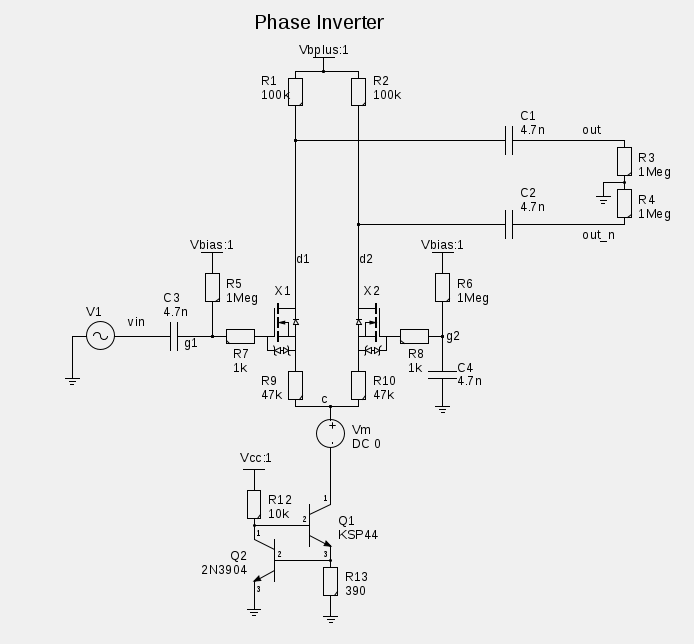
    I have my input and drive requirements working if I use a CCS. Replacing the CCS with a tail resistor appears to starve on either side of what I calculate the target resistance to be for the same idle current. The CCS should be drawing 1.7mA quiescent, and sitting at 47.3v with no signal, or a resistance of about 28k. But I haven't been able to find a resistor value that keeps it from either clipping or starving, while the CCS appears to work beautifully. Can I still meet all the requirements above with just a tail resistor?

    Edit: Bplus is 390V, Vbias is 90V
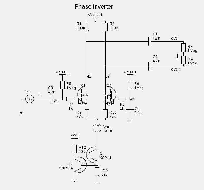
    Last edited by NateS; 03-21-2014, 02:55 AM.
    The prince and the count always insist on tubes being healthy before they're broken

  • #2
    If the CCS is used to set the current and there is Vbias on the gates, what're the purpose of R9 & R10? I don't know, just asking.

    Comment


    • #3
      It's local feedback to reduce the gain (and reduce miller effect, but it's WAY more than necessary for just that). It's also apparently the <ahem> SOURCE of the problem. Horowitz & Hill have perhaps the best treatment of differential amp's I've encountered so far. I'm reducing the gain (rather than padding and reamplifying), but they also seriously degrade common mode performance when they're as large as this - a matter which is remedied by my use of the CCS.

      It would appear that if you want to throttle down a differential amp to the degree I have here, that the CCS is absolutely essential. (First time I've encountered that.) It also removes the traditional NFB input but luckily I still have the non inverting side to work with. The massive gain reduction though means I'll need to reevaluate the feedback loop.
      Last edited by NateS; 03-21-2014, 02:06 PM.
      The prince and the count always insist on tubes being healthy before they're broken

      Comment


      • #4
        OK - I redrew the circuit to generate more interest
        The prince and the count always insist on tubes being healthy before they're broken

        Comment


        • #5
          I realize NFB is largely a suit to tast proposition, but I'd still like to shoot for similar levels as the 2204 as a starting point. It has 25db more gain in the phase inverter than I do, or does it? If you inject a signal into the tail I think it would be amplified by the common mode gain, rather than the differential gain. Since the non inverting input is ac coupled to the tail I don't know how to make heads or tails of it. The differential gain is more than the nfb divider reduces, so treating it as exlusively common mode input makes sense.
          The prince and the count always insist on tubes being healthy before they're broken

          Comment


          • #6
            I had always wondered why the feedback was returned to the tail + right input of the LTP and not just to the right input so one day I tried it and found that with the feedback only to the right input the output balance of the two sides was very poor.

            If it has 140V p-p coming out of the tone stack all you needs is a unity gain floating paraphase
            Last edited by Dave H; 03-22-2014, 10:30 AM.

            Comment


            • #7
              TBH I've never really paid attention to FPI's, but my first glance at Merlin's description leaves me with the impression that one is Stromboli and the other a Calzone. Almost the same ingredients, arranged slightly differently. Why floating paraphrase?
              The prince and the count always insist on tubes being healthy before they're broken

              Comment


              • #8
                Originally posted by Dave H View Post
                If it has 140V p-p coming out of the tone stack all you needs is a unity gain floating paraphase
                How do you get 140Vp-p after the TS? Not with the floating paraphase again!

                Comment


                • #9
                  Thats a later higher voltage preamp, vol set to 40% on a linear scale, 100mv input, and the tone controls set to midpoints. No visible clipping and just a tiny blip of 2nd harmonic visible on the fft. It doesn't look like floating paraphrase buys me anything much, two triodes and still has a ton of gain I need to trade away. I'm starting to like the idea of an active mixing stage, as I have some ideas for dynamic feedback controls I'd like to play with once its up and running.
                  The prince and the count always insist on tubes being healthy before they're broken

                  Comment


                  • #10
                    Still seems rather high, assuming average loss of the TMB TS of 10dB, that means the pre-TS, there is 140/0.316 = 443Vp-p?! Just how high was the B+ used on the preamp?

                    Comment


                    • #11
                      Design the preamp so it does not give 140V or use a voltage divider.

                      This is not a good design for high swing and very low gain phase inverter. By nature, differential pair like this has much higher gain than you want here. You have to lower the gain by large resistor value ( 47K) on R9 and R10. That by nature eat up voltage headroom. Then you have to have CCS to still making it a differential pair!!!

                      Comment


                      • #12
                        I'm going through the preamp with a finer tooth comb now, it does appear to be swinging a lot closer to the rail than it should be able to. And I can agree with not using a phase inverter which is inherently high gain. I can't really warm up to the idea of throwing away 25db of signal and then reamplifying it for no good reason. It's not a super high gain amp, but I'm still trying to ruthlessly eliminate noise source which don't have a darned good reason to be there.
                        The prince and the count always insist on tubes being healthy before they're broken

                        Comment


                        • #13
                          Maybe half way, low the swing some, divide some and then reduce R9 and R10 so you have more room to play. You might be able to get away from the transistor CCS.

                          Funny I am fighting the EXACT opposite problem. I only get about 10Vpp of clean signal from the preamp ( you get a lot less voltage from those Marshall Plexi type preamp). I need to get the power amp to clip and 40Vpp. I barely get it to clip after increasing the gain of the differential stage to increase the loop gain. Now I have to look for a little swing here and there to get a few more volts from the preamp!!!! I sure wish we can exchange problem!!!!

                          Comment


                          • #14
                            Ok, here's my analysis of the stock preamp, 100mV input, volume at 35% (linear), master cranked, and TMB at 5-5-5. (It doesn't look like anything close to 10db loss)


                            AC analysis - ak4 is the cathode follower output to the tone stack, pi_in is the input to the phase inverter after the master volume, which is wide open.


                            Here's a transient analysis - ab4 is the plate voltage of the follower, ak4 is the cathode voltage, and once again pi_in is the output of the master volume.


                            Looks like GOBS of swing, there's still almost 45V margin left across the the plate resistor of the last gain stage. Perhaps I'm driving the input too hard, but it looks like the preamp itself is capable of passing an undistorted signal of this magnitude. (I'm planning on slapping a clean TL072 buffer with pre-emphasis eq tweaked to match the first gain stage right at the jack. That's not in this simulation, but if all it lacks is drive.... I have tons to spare.)
                            Last edited by NateS; 03-24-2014, 03:00 AM.
                            The prince and the count always insist on tubes being healthy before they're broken

                            Comment


                            • #15
                              Originally posted by Alan0354 View Post
                              Maybe half way, low the swing some, divide some and then reduce R9 and R10 so you have more room to play. You might be able to get away from the transistor CCS.

                              Funny I am fighting the EXACT opposite problem. I only get about 10Vpp of clean signal from the preamp ( you get a lot less voltage from those Marshall Plexi type preamp). I need to get the power amp to clip and 40Vpp. I barely get it to clip after increasing the gain of the differential stage to increase the loop gain. Now I have to look for a little swing here and there to get a few more volts from the preamp!!!! I sure wish we can exchange problem!!!!
                              The phase inverter starts clipping around 8vpp IIRC. Are you sure its clipping before the phase inverter, and not in the phase inverter?

                              And by mixing stage - I was thinking about a local feedback inverting mosfet summing amp.
                              The prince and the count always insist on tubes being healthy before they're broken

                              Comment

                              Working...
                              X