 Tweet
Tweet
The thread 'JCM800 Downscale'
http://music-electronics-forum.com/t30501/
created a fair amount of interest a while back. The idea was to build a Marshall type of amp but there was a limit to the voltage that the amp could run at. It was for a university thesis and for safety sake they limited the voltage to 40V. I proposed using the 6AU6 as the gain stages rather than using triodes. I thought they would give more gain at low voltages and may sound better that the 12AX7 running at low voltages. I drew up a quick schematic as a starting point but it never got farther than that as I had other amps to build.
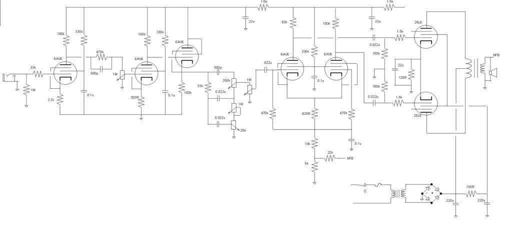
Well I got the other amps built and returned to this idea. The OP of the originating thread has gone on to bigger and better things so I had a blank slate to work with. I wanted to keep the voltage under 48V, in lot of jurisdictions that is considered a save voltage that you can not really hurt yourself badly. I wanted to use one transformer for the heaters and the power supply so I selected the 25L6 for the output tube which heater needs 25V. The 6AU6 also comes in a 12V version and putting a couple in series would allow a person to run them off the same winding. Another reason for using the 6AU6 is that I won an auction for 50 of the tubes at a low initial bid and have no real application for them.
I took an old chassis that I tried making a 100W SS amp in when I was in my teen's and mounted sockets, transformers, pots and a breadboard
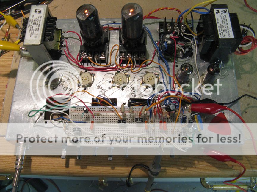
I used a bridge rectifier to get about 34V from the 24V transformer. Threw together a bias circuit for the output tube and did a input stage going to a LTP PI then to the output tubes. I originally thought of using a 70V line matching transformer (for intercom speakers in hospitals, schools, and the like) as a 10W one is suppose to have down to a 500 ohm winding when used in P-P. Putting together the test circuit I used a Hammond multitap transformer I had instead, thought it went down lower but for an 8 ohm load the lowest impedance it has is 3k. Good enough for a start, got the circuit working enough to see if it was worth bothering with.
Well it was pretty much not worth bothering with. Just not enough voltage to get enough volume out of the amp. While I had it set up I decided to try it at 50V. Passable for someone that had an efficient speaker and lived in an apartment block. I thought about using 35C5's which would get the dc voltage up to 50V, then thought what if you used a 12L6 and a voltage trippler? Could also use two 6AU6's in series or a 12AU6 directly across the transformer. See, it is feasible, good enough for me to try the full circuit.
With the test circuit I found to get the most volume out of the 25L6 I had to run the bias voltage around 3V, not a lot of headroom. I also found that the normal method of supplying the screens of the preamp tubes voltage with a resistor off the supply and with a capacitor to ground did not change the operation of the tube much and that I could just connect the screens to the supply. Makes for a lower parts count and complexity. Thought what is good for a preamp tube might be good for a power tube so I ran those off the supply also. Going to be hard getting to the screens dissipation limits running at these voltages. I also thought I could simplify the circuit by going cathode bias on the output tubes. Loosing three volts will not matter much and it lowers the complexity. I did give each tube their own cathode resistor as I wanted to know what each tube was drawing. I have a bunch of used tubes and found some are not all that healthy.
After spending some time getting the circuit to work I came up with the following values.
Not a lot of gain as compared to a Marshall but then again we don't have a lot of headroom to work with. I tried a higher plate resistor on the input tube but it sounded a little ratty. I did not have the tone stack working, I think I have a bad treble pot. In place of the stack I put a 1M pot in as a volume control. As little the amount of gain it is easy to overload the PI without any attenuation. Probably will lose the mid pot when I get back to looking at this project and putting in the tone controls. Too many other things I should be doing at this time of year.
http://music-electronics-forum.com/t30501/
created a fair amount of interest a while back. The idea was to build a Marshall type of amp but there was a limit to the voltage that the amp could run at. It was for a university thesis and for safety sake they limited the voltage to 40V. I proposed using the 6AU6 as the gain stages rather than using triodes. I thought they would give more gain at low voltages and may sound better that the 12AX7 running at low voltages. I drew up a quick schematic as a starting point but it never got farther than that as I had other amps to build.
Well I got the other amps built and returned to this idea. The OP of the originating thread has gone on to bigger and better things so I had a blank slate to work with. I wanted to keep the voltage under 48V, in lot of jurisdictions that is considered a save voltage that you can not really hurt yourself badly. I wanted to use one transformer for the heaters and the power supply so I selected the 25L6 for the output tube which heater needs 25V. The 6AU6 also comes in a 12V version and putting a couple in series would allow a person to run them off the same winding. Another reason for using the 6AU6 is that I won an auction for 50 of the tubes at a low initial bid and have no real application for them.
I took an old chassis that I tried making a 100W SS amp in when I was in my teen's and mounted sockets, transformers, pots and a breadboard
I used a bridge rectifier to get about 34V from the 24V transformer. Threw together a bias circuit for the output tube and did a input stage going to a LTP PI then to the output tubes. I originally thought of using a 70V line matching transformer (for intercom speakers in hospitals, schools, and the like) as a 10W one is suppose to have down to a 500 ohm winding when used in P-P. Putting together the test circuit I used a Hammond multitap transformer I had instead, thought it went down lower but for an 8 ohm load the lowest impedance it has is 3k. Good enough for a start, got the circuit working enough to see if it was worth bothering with.
Well it was pretty much not worth bothering with. Just not enough voltage to get enough volume out of the amp. While I had it set up I decided to try it at 50V. Passable for someone that had an efficient speaker and lived in an apartment block. I thought about using 35C5's which would get the dc voltage up to 50V, then thought what if you used a 12L6 and a voltage trippler? Could also use two 6AU6's in series or a 12AU6 directly across the transformer. See, it is feasible, good enough for me to try the full circuit.
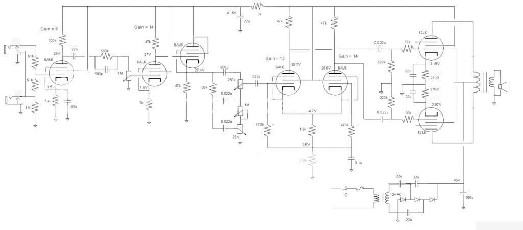
With the test circuit I found to get the most volume out of the 25L6 I had to run the bias voltage around 3V, not a lot of headroom. I also found that the normal method of supplying the screens of the preamp tubes voltage with a resistor off the supply and with a capacitor to ground did not change the operation of the tube much and that I could just connect the screens to the supply. Makes for a lower parts count and complexity. Thought what is good for a preamp tube might be good for a power tube so I ran those off the supply also. Going to be hard getting to the screens dissipation limits running at these voltages. I also thought I could simplify the circuit by going cathode bias on the output tubes. Loosing three volts will not matter much and it lowers the complexity. I did give each tube their own cathode resistor as I wanted to know what each tube was drawing. I have a bunch of used tubes and found some are not all that healthy.
After spending some time getting the circuit to work I came up with the following values.
Not a lot of gain as compared to a Marshall but then again we don't have a lot of headroom to work with. I tried a higher plate resistor on the input tube but it sounded a little ratty. I did not have the tone stack working, I think I have a bad treble pot. In place of the stack I put a 1M pot in as a volume control. As little the amount of gain it is easy to overload the PI without any attenuation. Probably will lose the mid pot when I get back to looking at this project and putting in the tone controls. Too many other things I should be doing at this time of year.
 . Pentodes seem to require rather large screen voltages, so I think some triodes might be better suited to this. I tried this with a 6as7g, but it just required too much drive voltage and I couldn't even force the thing into clipping - put out a decent amount of power though.


Comment