Ad Widget

Collapse

Announcement

Collapse
No announcement yet.

Help understanding output transformer primary impedance

Collapse
X
 
  • Filter
  • Time
  • Show
Clear All
new posts

  • #16
    Originally posted by Alan0354 View Post
    There is not too many OT primary impedance to choose and it's not particular important to be exact. Standard common ones are about 2K, 4K, 8K, 3.4K and I think 1.7K. For common +B of 400 to 450V, 2 6V6, use 8K. For 2 6L6, use 4K. 4 6L6, use 2K. Then for 2 EL34 use 3.4K like in Marshall Plexi.
    At this point in my journey (still early), I'll disagree with the view that one must pick common p-p impedances. The tubes will work over a wide range of impedances.


    Originally posted by R.G. View Post
    On the other hand, the tubes themselves are not terribly fussy about the plate to plate load, and differences of 2:1 still work, albeit with different frequency responses into particular speakers, different distortion curves, and mildly different power outs - generally not enough difference in power out to make a huge difference to apparent volume.
    I'd like to follow up on this to find out more. First, by 2:1, do you mean a change in primary impedance of 2:1 (or 1:2)?

    Second, are there predictable changes in frequency responses when you change primary impedances?

    Example with some uncommon p-p values: I built a 2xEL34 project amp with an OT I had handy, which had a 10k primary impedance and 4R, 8R, and 16R secondaries. I connected my 8R speaker cab to the 8R output jack and then to the 16R jack (to get an effective primary impedance of 5k). To my ears, the mismatch (5k primary) yielded a clearer overdrive*, more high end, and a woodier tone (less mids?). The nominal match (10k primary) yielded more distortion, less high end, and a thicker sound. Is this what one would/should expect from changing the primary impedance from 5k to 10k with a pair of EL34s?

    *the preamp is a hot-rodded JCM800; gain was set at noon
    Last edited by stormbringer; 09-25-2014, 05:22 AM.

    Comment


    • #17
      Originally posted by stormbringer View Post
      Second, are there predictable changes in frequency responses when you change primary impedances?
      Read this classic post from R.G.

      Comment


      • #18
        Originally posted by stormbringer View Post
        At this point in my journey (still early), I'll disagree with the view that one must pick common p-p impedances. The tubes will work over a wide range of impedances.
        It all depends on how you parse the language. I believe that the posters were stating that you can only get OTs which are wound to reflect nominal 4, 8, and 16 ohm loads to a few nominal values of plate to plate. Those are all that are manufactured. So as a practical matter, you're either winding your own transformers or picking one of the stock ones. That then leads to the observation that there are only a few choices, not infinitely many.

        Transformers don't have impedances, they have ratios. Output transformers got dumbed down to stating impedances back in the 50s and it stuck. The guitar amplifier world is busy trying to recreate all the knowledge that was there before the info was dumbed down. So yes, it's theoretically possible to have any ratio of impedances. As a practical matter, they're not available that way.

        But they do have ratios. A transformer that converts 8 ohms on the secondary to 4400 ohms on the primaries has a ratio of 4400 to 8, or 550. The voltage (and turns) ratio is the square root of that, or 23.5. And that's what the transformer reflects. If you load this transformer with three 16 ohm speakers in parallel, you get 5.33 ohms on the secondary and 2931.5 ohms plate to plate. If you load it with a 100 ohm resistor, you get 55K plate to plate. Same transformer. The tubes still work, the transformer works, but you still had to *buy* a 4400 to 8 ohm transformer to get there.

        I'd like to follow up on this to find out more. First, by 2:1, do you mean a change in primary impedance of 2:1 (or 1:2)?
        Actually, either way.

        Second, are there predictable changes in frequency responses when you change primary impedances?
        Yes, but you have to dig into transformer modelling and math. A really good model of the frequency response of an OT can be done if you know the loading accurately (i.e. the real RLC characteristics, not "8 ohms" or "16 ohms"), the transformer ratio, the transformer leakage inductance, the transformer primary inductance, and the self resonant frequency of the primary. Those things can be used to produce an expected result. Notice that in general you're not changing primary impedances. You're substituting whole transformers which may be dramatically different in primary inductance, leakage, resonance, and so on.

        And in general, you're not changing primary impedances if you mess with the secondary loading. You're leaving all the transformer stuff the same, and only changing what is reflected from the secondary and how it interacts with the pre-existing primary inductance and other things.

        That's all to say, no, you can't say "OK, I want a little more top end, so I'll change the primary impedance from 4400 to 6600". Well, you can say that, but you'd be wrong, or only accidentally correct. It's more complicated than that, many interacting factors.

        As a practical matter, changing speakers at the SAME impedance has a much bigger effect on the frequency response. Speakers are like opera singers. They may hit the same notes, but they sound different.

        To my ears
        Ears are a terribly deficient instrument for measuring frequency response. They're really good for getting fast impressions and identifying what may be a saber toothed tiger stalking you. Not so good for plotting burbles in high end and "presence".
        Amazing!! Who would ever have guessed that someone who villified the evil rich people would begin happily accepting their millions in speaking fees!

        Oh, wait! That sounds familiar, somehow.

        Comment


        • #19
          The real Hi Fi guys (not snake oil salesmen but seasoned "boring" Engineers) know this very well, and can provide the real answers.

          Pity they are often complex and expensive and require hard work.

          It's easier to offer capacitors made out of Ming Emperor's gown silk, silver from mint 1875 US coins and wax from radioactive bees which make nests in the Chernobyl reactor ruins .

          This is a real example of a very well made auto transformer, to adapt any possible speaker load to a lot of power amp different optimum impedances.

          To avoid having 200 taps, it has multiple windings which come out to terminal strips, and they provide a table so you can combine them in endless ways.
          As in from 0.2 ohms to 32 ohms with 64 ohms possible :

          the "layout" :


          the "schematic" :


          the actual beast:


          doesn't LOOK like a NASA thingie or something made by Tibetan Monks 4000 meters high in the Himalayas, huh?

          Pity that the only thing it has to offer is PERFORMANCE:
          Test Results.
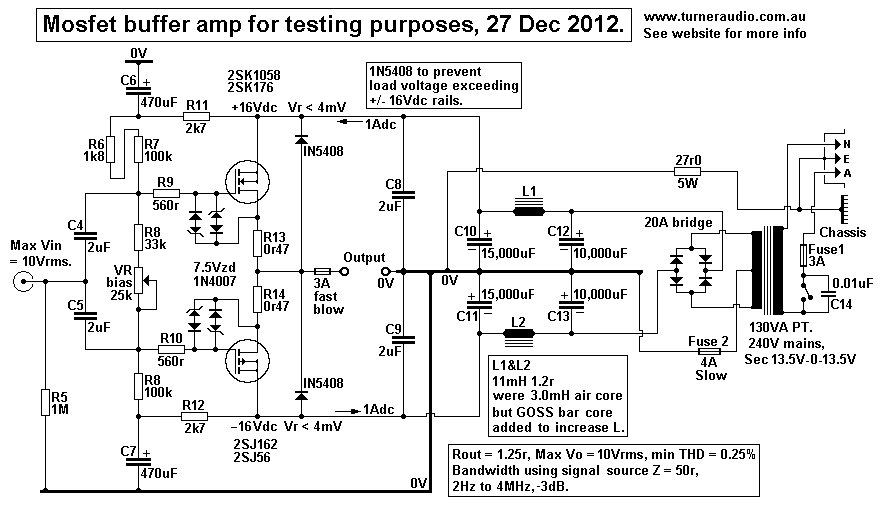
          I tested the above transformer using the mosfet buffer and 3Vrms sine wave signal source generators giving
          2Hz to 4MHz bandwidth, with Rout of buffer = 1.3ohms.
          With no load of any kind connected, bandwidth for between G&H was dead flat from well below 10Hz to
          1MHz, with a =1dB peak at 900kHz. There was a peak of +3dB at 2MHz and then output declined at
          more than 12dB/octave
          with other peaks and nulls of lessening levels.
          Don't misunderstand the above statements: when testing a transformer of any kind, the worst test condition is no load, because all internal resonances, peaks, ringing shows in full.
          While a resistive load can and will damp them in varying degrees.

          To be able to measure it he had to build a special very flat Mosfet buffer, driven sraight from a generator which sweptt from 2 Hz to 4 MHz, any conventional amp would have introduced its own limitations.
          Juan Manuel Fahey

          Comment


          • #20
            Originally posted by J M Fahey View Post
            The real Hi Fi guys (not snake oil salesmen but seasoned "boring" Engineers) know this very well, and can provide the real answers.

            Pity they are often complex and expensive and require hard work.

            It's easier to offer capacitors made out of Ming Emperor's gown silk, silver from mint 1875 US coins and wax from radioactive bees which make nests in the Chernobyl reactor ruins .

            This is a real example of a very well made auto transformer, to adapt any possible speaker load to a lot of power amp different optimum impedances.

            To avoid having 200 taps, it has multiple windings which come out to terminal strips, and they provide a table so you can combine them in endless ways.
            As in from 0.2 ohms to 32 ohms with 64 ohms possible :

            the "layout" :


            the "schematic" :


            the actual beast:


            doesn't LOOK like a NASA thingie or something made by Tibetan Monks 4000 meters high in the Himalayas, huh?

            Pity that the only thing it has to offer is PERFORMANCE:

            Don't misunderstand the above statements: when testing a transformer of any kind, the worst test condition is no load, because all internal resonances, peaks, ringing shows in full.
            While a resistive load can and will damp them in varying degrees.

            To be able to measure it he had to build a special very flat Mosfet buffer, driven sraight from a generator which sweptt from 2 Hz to 4 MHz, any conventional amp would have introduced its own limitations.
            Cool. 8-)
            Building a better world (one tube amp at a time)

            "I have never had to invoke a formula to fight oscillation in a guitar amp."- Enzo

            Comment

            Working...
            X