Ad Widget

Collapse

Announcement

Collapse
No announcement yet.

OT Windings

Collapse
X
 
  • Filter
  • Time
  • Show
Clear All
new posts

  • #16
    Originally posted by Malcolm Irving View Post
    Agreed. But I think there is a very slight advantage to using a 16 ohms speaker on the full 16 ohm secondary winding, compared to say a 4 ohm speaker on a 4 ohm tap.

    The 4 ohm tap uses half of the secondary turns, so the resistance of the secondary winding being used is half (OK maybe not exactly, depending on which turns are 'on the inside track').
    Sorry but that's not the case.
    You think both windings use same diameter wire .
    The 4 ohms winding uses half the available turns, but also 40% thicker wire, so half resistance per turn.

    And that, in guitar OPT, or general purpose ones; in Hi Fi types (or some Pro PA ones), there are not 4/8/16/whatever windings per se, but a bunch (at least 2 but might be up to a dozen) of independent windings connected to a patch plate, and there you combine them in series/parallel as needed to get whatever impedance.

    In that case, it would have 2 x "4 ohms " impedance windings, which are used in parallel for 4 ohms and in series for 16 ohms.


    The current when we use the 4 ohm tap is twice what we would have using the 16 ohm tap, for the same speaker power output. Combining these two factors, we find the power loss in the secondary winding when using the 4 ohms tap is 0.5x2x2 = twice what it would be if we used the 16 ohm option.

    So using the 16 ohm option, reduces the heat in the secondary winding and allows a tiny bit more power through to the speaker.
    See above.

    OK, if we carry this further, what about the choice of 4 ohm vs 16 ohm voice coils in two speakers? What are the power implications in those choices. Does one of the VCs get hotter than the other at the same sound output?
    No, power dissipatedis the same, radiation and convection surface is the same, so temperature rises by the same amount in both.

    The only difference is that the 16 ohms coil is lighter than an 8 or 4 ohms one; speaker is not louder but may be snappier, brighter.
    Juan Manuel Fahey

    Comment


    • #17
      Originally posted by J M Fahey View Post
      ....
      The 4 ohms winding uses half the available turns, but also 40% thicker wire, so half resistance per turn.
      ....
      Thanks for explaining that. I had not realised that.

      Comment


      • #18
        Originally posted by J M Fahey View Post
        In that case, it would have 2 x "4 ohms " impedance windings, which are used in parallel for 4 ohms and in series for 16 ohms.
        I think you mean 2 X 8 ohm, right?

        Originally posted by J M Fahey View Post
        The only difference is that the 16 ohms coil is lighter than an 8 or 4 ohms one; speaker is not louder but may be snappier, brighter.
        Why is 16 ohm lighter? you might have thinner wires, but more turns.

        Comment


        • #19
          Originally posted by Alan0354 View Post
          I think you mean 2 X 8 ohm, right?
          No, I'm sure he means 2 x 4 ohm. It doesn't work like resistors in parallel. 2 x 4 ohm windings in parallel is still 4 ohms as it's effectively the same number of turns as a single 4 ohm winding.

          Comment


          • #20
            Originally posted by Dave H View Post
            No, I'm sure he means 2 x 4 ohm. It doesn't work like resistors in parallel. 2 x 4 ohm windings in parallel is still 4 ohms as it's effectively the same number of turns as a single 4 ohm winding.
            Ha, never thought of that, really learning something today. Thanks

            Comment


            • #21
              Originally posted by Alan0354 View Post
              I think you mean 2 X 8 ohm, right?
              No, I meant 2 x 4 ohms ones.

              In transformers the main parameter is voltage across winding ends and not wire resistance.

              Practical example: an OT has 2 x 10 Volt windings, obviously same amount of turns and wire diameter each and so same DC resistance .... which is much lower than expected load impedance.
              Say each winding has 0.2 ohms DC resistance.

              Let's see 3 cases:

              1) both windings in parallel, loaded with 4 ohms:
              P=V^2/Z = 10*10/4=100/4=25W .

              Resistive losses: you will have 2 x 0.2 ohms resistors in parallel, or 0.1 ohms total, in series with 4 ohms load, so you lose 1/40 output power .

              2) both windings in series, loaded with 16 ohms:
              P=V^2/Z=20*20/16=400/16=25W

              Resistive losses: you will have 2 x 0.2 ohms resistors in series, or 0.4 ohms total, in series with 16 ohms load, so you still lose 1/40 output power .

              As you see, 2 equal windings allow 4/16 ohms, but not 8 .
              Or allow 2/8 ohms , always 4:1 impedance ... because options are 2:1 voltage.

              3) now, what happens if we load just 1 winding with an 8 ohms speaker?
              Is it an "8 ohms winding" ?
              well, we'll still have 10 V across it, which will provide 10*10/8=100/8=12.5W .

              We are not getting the 25W the amp can produce so, yes, we can connect an 8 ohms speaker there but we can not call that a matched load, at all.

              In a nutshell: in a transformer first "think voltage" , then convert that into impedance.

              And those Hi fi /PA transformers I mentioned, offer, say, at least 2 "10V"windings and one "4V" winding (or whatever matches amp power out) and combining them in series/parallel adapt to many impedances.

              Remember those Bogen amps we saw short time ago which offered 4/8/16 ohms, plus 25V and 70V balanced/unbalanced power outputs or the Geloso amplifiers which offered anything between 1.25 ohms and 500 ohms, plus 100V lines .

              I've seen C core , Hi Fi transformers which had, say, 12 (or thereabouts) "4V" windings which could be wired in a ton of series/parallel configurations, in that case to get standard 4/8/16 ohms output but varying primary impedance , say from 1600 to 12k ohms , to adapt to anything, from 2A3 to 807 tubes and anything in between.

              Why is 16 ohm lighter? you might have thinner wires, but more turns.
              Yes, you have thinner wire, so you have more turns, but section, weight,amount of turns are not directly proportional

              A simple example:

              Suppose you have a
              a) 100 turn voice coil,
              b0 it weighs, say, 2 grams and
              c) has 8 ohms DCR

              Now you wind another, on a form same height and diameter , but use half diameter wire.

              Now
              d) you will be able to fit 200 turns in the same space, (2:1 ratio) <-- easy
              e) it will weigh half as before (2:1 ratio) <-- why?
              f) total resistance will be 64 ohms (8:1 ratio) <-- no, not a typo

              Unexpected, huh?

              I'lll let the most Math inclined (and/or masochists) here find why.

              If not, I'll post the answer later.


              FWIW: at the beginning I could not believe my own Math, until it "clicked" .

              As said often: "practice makes perfect" , and since I do have to design custom voice coils for my own speakers and repairs which arrive with them turned into a messy piece of charcoal, I'm quite proficient by now.
              Juan Manuel Fahey

              Comment


              • #22
                Originally posted by J M Fahey View Post
                Resistive losses: you will have 2 x 0.2 ohms resistors in parallel, or 0.1 ohms total, in series with 4 ohms load, so you lose 1/40 output power.
                Shouldn't that be "you lose 1/40 output voltage therefore 1/80 output power" ?

                Comment


                • #23
                  Originally posted by J M Fahey View Post
                  A simple example:

                  Suppose you have a
                  a) 100 turn voice coil,
                  b0 it weighs, say, 2 grams and
                  c) has 8 ohms DCR

                  Now you wind another, on a form same height and diameter , but use half diameter wire.

                  Now
                  d) you will be able to fit 200 turns in the same space, (2:1 ratio) <-- easy
                  e) it will weigh half as before (2:1 ratio) <-- why?
                  f) total resistance will be 64 ohms (8:1 ratio) <-- no, not a typo

                  Unexpected, huh?

                  I'lll let the most Math inclined (and/or masochists) here find why.
                  Masochist here.

                  e) It's twice as long but half the diameter or 1/4 the area which means it's 2 x 1/4 = 1/2 the weight.
                  f) 1/4 the area means 4 x the resistance x twice as long = 8 x the resistance

                  Comment


                  • #24
                    Originally posted by J M Fahey View Post
                    No, I meant 2 x 4 ohms ones.

                    In transformers the main parameter is voltage across winding ends and not wire resistance.
                    Yes, I wasn't thinking. Totally forgot it's transformer. Too distracted because both my grandson and grand daughter are staying with us AND I have to hook up a new printer!!! !! My old Canon just broke down and I bought a new Canon just one model up. Thinking that it's an easy transition......WRONG. It can't be more different from the old one. I have to go online to read everything!!! So I am out of commission for a day or two, the printer is my life line, I can't read on the computer because I have severe neck problem, I have to print things out to read. Even some of the long post from you guys, I have to print it out to read.

                    Comment


                    • #25
                      Originally posted by Dave H View Post
                      Shouldn't that be "you lose 1/40 output voltage therefore 1/80 output power" ?
                      I'll write the long explanation instead of just throwing a naked formula on the table

                      1) To make a precise calculation, I should have calculated new total resistance, then voltage drop in each, then "new" power( we no longer have the expected original value) , etc.

                      Since that's not the point "today", but there's another more important one (transformer secondaries), I simplified the analysis for main concept clarity.

                      Otherwise people would be lost on numbers with many decimal places (just do the Math) and would have been distracted from the main concept.

                      And remember I introduced wire resistance, to make a better explanation
                      No good deed goes unpunished

                      I have been accused by nitpickers of "butchering explanations"
                      (sic) ; specially at DIY Audio (the home of snake oil believers, by the way ) .

                      Fact is : I'm an Engineer, not a Physicist.

                      Physicists worry about 0.0000005% variation in measured speed velocity whether it passed close to a certain star or not and based on that calculate star mass.
                      Fine, it's the nature of their work.

                      Engineers calculate how many bolts are needed to hold 2 bridge structure I beams together and when structural stress result is 42.1 bolts, they have to choose between 42 and 43, bolts are not available on 0.1 increments ... in fact will specify 46 "just in case" .
                      Different approaches to sometimes similar problems.

                      2) FWIW , and this was a decision taken on purpose, I simplified but I'm not crazy, I can take some risks impunely when I know that "voy a caer parado" : "I'll fall standing/on my feet" .
                      What do I mean?

                      In this case, winding resistance is in series with a much larger one, which is the one which will dominate current.
                      If I apply voltage to load+winding, it's the load which will dominate so it will set current.

                      So 10V/4 ohms means 2.5A

                      Power is I^2*R and current is the same through both resistors (load and winding)

                      I^2 is 2.5*2.5=6.25 A^2
                      I is the same on both, so I^2 is also the same on both

                      Power on the 4r load is: 6.25*4=25W (a Physic would say (correctly) that current is not 2.5A but somewhat less, because now we have 4.1 ohms instead of 4 ... and he'd be right .... simply such precision is not relevant today to understand the main concept)

                      Power on the 0.1r load is 6.25*0.1=0.625W

                      Simple Math tells us that 25/0.625=40 and we are talking power here, so 0.1r dissipates 1/40 of the power dissipated on the load.
                      Which is what I wrote.

                      3) to leave no stone unturned, let's recalculate using voltage.

                      10V total, applied to 4+0.1 ohms

                      [rounding numbers ahead warning]

                      Voltage drop across 0.1 ohms=10/40.1*.1=0.25V (yes, I should have written 0,0249376558603491 , I warned I'm a lazy Engineer )

                      Power dissipated in 0.1 ohms is V^2/r=: 0.25*0.25/0.1=0.0625/0.1=0.625W <-- same as before.

                      And still 1/40 of 25W .
                      Juan Manuel Fahey

                      Comment


                      • #26
                        Originally posted by Alan0354 View Post
                        Yes, I wasn't thinking. Totally forgot it's transformer. Too distracted because both my grandson and grand daughter are staying with us AND I have to hook up a new printer!!! !! My old Canon just broke down and I bought a new Canon just one model up. Thinking that it's an easy transition......WRONG. It can't be more different from the old one. I have to go online to read everything!!! So I am out of commission for a day or two, the printer is my life line, I can't read on the computer because I have severe neck problem, I have to print things out to read. Even some of the long post from you guys, I have to print it out to read.
                        Ouch !!!!!!

                        That said, we DESERVE a picture of your beautiful grandkids wreaking havoc on grandpa's lab/livingroom/whatever
                        Juan Manuel Fahey

                        Comment


                        • #27
                          Originally posted by Dave H View Post
                          Masochist here.

                          e) It's twice as long but half the diameter or 1/4 the area which means it's 2 x 1/4 = 1/2 the weight.
                          f) 1/4 the area means 4 x the resistance x twice as long = 8 x the resistance
                          COOOOLLLLLLLL !!!!!!
                          I was quite certain you would answer

                          FWIW it took me sometime to realize that DCR was a cubic function of wire diameter.

                          I did calculate it properly before, just wire table,pen, pencil and simple calculator , until I wrote a BASIC program to calculate and print a VC typical size values in any impedance and length

                          Yup, BASIC, it was early 1970's before PCs appeared, even before Tandy and Sinclair.

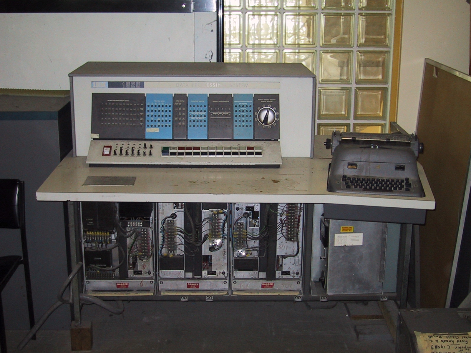
                          I carried it to the University to be processed by an IBM1620


                          Where's the monitor screen you say?

                          Screen? .... what screen?

                          It ain't no f****ng TV !!!!!!

                          Next you will also pretend these will be used to play ..... Music !!!!!!

                          Juan Manuel Fahey

                          Comment


                          • #28
                            Got interested in the 1620 & found this nice 'Computer History Timeline' link: Computer History Museum | Timeline of Computer History
                            It stops at 1994

                            And some interesting info on the 1620: https://www.cs.auckland.ac.nz/histor...BM1620Main.php

                            Comment


                            • #29
                              Originally posted by J M Fahey View Post
                              ... processed by an IBM1620 ...Where's the monitor screen you say?...
                              Actually, I was wondering "where's the card reader?" Those were really cool machines. With all the register lights on the front panel it put on a great display when the machine was running.

                              Thanks for the links Jazz
                              Last edited by Tom Phillips; 12-30-2014, 06:23 PM.

                              Comment


                              • #30
                                Originally posted by J M Fahey View Post
                                Ouch !!!!!!

                                That said, we DESERVE a picture of your beautiful grandkids wreaking havoc on grandpa's lab/livingroom/whatever
                                Thanks, I have the time of my life when they both are staying with us. But they both will be going home after New Years!!!

                                Attached is a picture on my wife's 70th birthday.

                                Alan
                                Attached Files

                                Comment

                                Working...
                                X