Ad Widget

Collapse

Announcement

Collapse
No announcement yet.

Princeton Semi-Clone Output X-Fmr?

Collapse
X
 
  • Filter
  • Time
  • Show
Clear All
new posts

  • #31
    Now I see the 25k! I was really scratching my head there. If the goal is just to drain off the filter caps for working on the amp, I agree that it should be swapped to a higher value -- right now, it's gobbling up 15mA of current and dissipating 5.5W of heat unnecessarily whenever the amp is on.

    As for the rectifier wiring, things are just fine with a 5Y3 or 5U4. My tangential post is relevant when you have a 5V4 or GZ34/5AR4 where the cathode is connected to one side of the heater, like this:
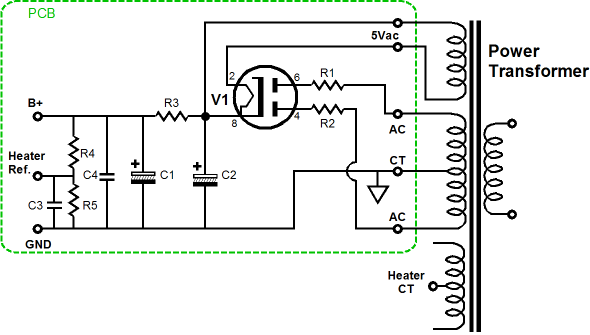

    (picture robbed from Tubecad.com)

    If you take B+ from pin 2, then you are creating a small potential difference between the cathode and that end of the heater, which at best adds a little ripple to your B+, and at worst stresses the heater-cathode insulation. I bring it up not to scold you, but just to suggest a better practice. Old Mullards were tough, newer rectifier tubes need a little babying, unfortunately.

    Comment


    • #32
      Ah, I see.
      Originally posted by ThermionicScott View Post
      ...I bring it up not to scold you, but just to suggest a better practice. Old Mullards were tough, newer rectifier tubes need a little babying, unfortunately.
      I didn't take it that way. I really welcome everyone's ideas. This is my very first guitar amp build.
      I have built hifi type amps, radio equipment, control systems, and even plenty of homebrew electronics test equipment.
      I have formal training in electricity/electronics, and many years of combined experience (mostly industrial)--but guitar amps are a different animal and I will take all the advice I can get. Doesn't mean I will necessarily follow all of it, as I have my reasons for doing things my way, but I will incorporate many ideas in the next build or possibly mod this one a little more if the new owner wants me to.

      No better way to learn some of these things than by "talking" to experienced enthusiasts like you all.

      Cheers,
      Rob
      robsradioactive.com

      Comment


      • #33
        Originally posted by ThermionicScott View Post
        Now I see the 25k! I was really scratching my head there. If the goal is just to drain off the filter caps for working on the amp, I agree that it should be swapped to a higher value -- right now, it's gobbling up 15mA of current and dissipating 5.5W of heat unnecessarily whenever the amp is on.
        I have a Fender 'Super 60' that has the same thing; a 30k high-wattage resistor on B+ (or one of the PSU nodes). My pet hypothesis is that it's there to mellow out the amount of sag in the supply, adding a small constant load under both idle and max power conditions.
        If it still won't get loud enough, it's probably broken. - Steve Conner
        If the thing works, stop fixing it. - Enzo
        We need more chaos in music, in art... I'm here to make it. - Justin Thomas
        MANY things in human experience can be easily differentiated, yet *impossible* to express as a measurement. - Juan Fahey

        Comment


        • #34
          Originally posted by eschertron View Post
          I have a Fender 'Super 60' that has the same thing; a 30k high-wattage resistor on B+ (or one of the PSU nodes). My pet hypothesis is that it's there to mellow out the amount of sag in the supply, adding a small constant load under both idle and max power conditions.
          My guess is that that 'HT potential divider' arrangement is intended allow 500V caps to be used downstream of the screen grid node; many Fenders from the late 70s / early 80s used very high HT voltage, eg >=500V.
          I seem to remember that they are also good at turning the PCB around them a nice brown colour?
          http://bmamps.com/Schematics/fender/...ice_Manual.pdf
          My band:- http://www.youtube.com/user/RedwingBand

          Comment


          • #35
            Originally posted by pdf64 View Post
            My guess is that that 'HT potential divider' arrangement is intended allow 500V caps to be used downstream of the screen grid node; many Fenders from the late 70s / early 80s used very high HT voltage, eg >=500V.
            I seem to remember that they are also good at turning the PCB around them a nice brown colour?
            http://bmamps.com/Schematics/fender/...ice_Manual.pdf
            Yes When I acquired the amp, that resistor's cement was cracked. It was 'stood off' from the PCB, so not a real nut brown color, but marked. Replaced it with a metal-housed resistor. High voltage ratings are a good notion. I hadn't looked at any spec'd or measured voltages though. I could calculate the current through each node resistor based on the spec'd voltages, then re-calculate the voltages at each node without the 30k resistor to see where the voltages rise to. Might be an interesting thought experiment. But not today.
            If it still won't get loud enough, it's probably broken. - Steve Conner
            If the thing works, stop fixing it. - Enzo
            We need more chaos in music, in art... I'm here to make it. - Justin Thomas
            MANY things in human experience can be easily differentiated, yet *impossible* to express as a measurement. - Juan Fahey

            Comment


            • #36
              Originally posted by Rob's Radio-Active View Post
              Here it is, less the new speaker.
              I tried to make it easy to service. Everything can be accessed under the top, back panel. I included test points for cathode current on the 6V6 tubes.
              Any DC mV measured on the test points to ground directly indicates cathode current in mA across their 1% tolerance, 1 ohm resistors.

              The "extra" controls/circuits are DRIVE, BIAS, and FEEDBACK.
              Drive is pretty obvious--it allows mild to severe clipping at low, or any, volume levels, or clean play through.
              Bias allows warmer or cooler tone within normal limits of 6V6 idle current choices.
              Feedback simply controls the amount of negative feedback for either a "looser" livelier response or more of a Hi-Fi type low, midrange, and treble relationship.

              (The keen eye will see that I flipped the control decaling over the other way. The owner-to-be hates reading upsidedown.)

              Cheers
              Rob
              Beautiful work, Rob!

              ...and points for thinking outside the norm and having controls not generally present for the user.
              If it still won't get loud enough, it's probably broken. - Steve Conner
              If the thing works, stop fixing it. - Enzo
              We need more chaos in music, in art... I'm here to make it. - Justin Thomas
              MANY things in human experience can be easily differentiated, yet *impossible* to express as a measurement. - Juan Fahey

              Comment


              • #37
                Originally posted by eschertron View Post
                I have a Fender 'Super 60' that has the same thing; a 30k high-wattage resistor on B+ (or one of the PSU nodes). My pet hypothesis is that it's there to mellow out the amount of sag in the supply, adding a small constant load under both idle and max power conditions.
                Originally posted by pdf64 View Post
                My guess is that that 'HT potential divider' arrangement is intended allow 500V caps to be used downstream of the screen grid node; many Fenders from the late 70s / early 80s used very high HT voltage, eg >=500V.
                I seem to remember that they are also good at turning the PCB around them a nice brown colour?
                http://bmamps.com/Schematics/fender/...ice_Manual.pdf
                That thought crossed my mind during this discussion, too. Voltage dividers aren't perfect, but they do offer a little better voltage regulation than the series dropping resistors you usually see in guitar amps. Shame they aren't employed more often, but I'm guessing the cost of the "shunt-leg-resistor" gets vetoed by the bean counters.

                Comment


                • #38
                  Thank, eschertron! The cabinet I bought--the really pretty part.
                  I would like to learn to make those, but I am more a metal guy; not much of a carpenter or cabinet maker.

                  Cheers,
                  Rob
                  robsradioactive.com

                  Comment

                  Working...
                  X