Announcement

Collapse
No announcement yet.

Biased diode clipping Q

Collapse
X
 
  • Filter
  • Time
  • Show
Clear All
new posts

  • #16
    Originally posted by J M Fahey View Post
    This is what killer Marshall 18 does when overdriven:
    Still looks like that with the PR mod.
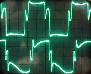
    It doesn't do anything on low volumes, just when the output tubes are already overdriven. It just clips the negative part of the waveform that you don't need anyway in "class B". On classic Marshalls (5881/EL34) the PI does the same, and nobody is complaining about them

    Agree with snubbers and bright caps tough, the amp has to sound a little "rude" with other instruments around

    Comment


    • #17
      Originally posted by nosaj View Post
      Explain the difference between this:

      i have to say all I see is a sad tube.

      nosaj
      The dog ate my homework!!!!!!! .... errrrrrrr ...... the Forum ate my image !!!!!!Now corrected .... although in any case the link was still there , just not displayed as an image .
      Clicking on it would have displayed it on another tab anyway.

      That said, fully agree that similarities are easier to see when they are side by side. (or top to bottom).

      As of:
      But thanks for beating up my design
      I was mistaken, I would have never ever criticized it if I ever thought it was yours

      Worst case would have said nothing.
      Juan Manuel Fahey

      Comment


      • #18
        A typical long-tail-pair PI provides more than enough voltage swing to seriously overdrive an EL84 push-pull stage. If you like that sound, it’s great and not a problem.

        Not sure why, but when you build a doubled-up version with 4 x EL84 for 36 Watt, the overdriven sound seems to smooth out a bit (maybe it’s the beefier OT?)

        Another way to make the output stage sound more like a big-bottle fixed-bias set up is to remove the cathode bypass cap(s) from the EL84s. The local negative feedback then means that more voltage swing from the PI is needed before the output stage gets overdriven. I think it also reduces the output power a little, because the cathode bias resistor(s) are now included in the AC load on the EL84s. But, you have to watch out that there is still enough drive to the power tubes to reach your desired output level.

        Comment


        • #19
          Originally posted by Malcolm Irving View Post

          Another way to make the output stage sound more like a big-bottle fixed-bias set up is to remove the cathode bypass cap(s) from the EL84s.
          Use fixed bias instead.

          Comment


          • #20
            Fixed bias would certainly be a good way to get the fixed-bias sound.

            But it won’t give you the ‘big-bottle effect’. An EL84 only needs about 15V swing on the grid to go from grid-limiting to cut-off, while an EL34 needs about 40V or so. By ditching the cathode bypass cap you now need 40V swing for the EL84.

            Comment


            • #21
              Originally posted by Malcolm Irving View Post
              Fixed bias would certainly be a good way to get the fixed-bias sound.

              But it won’t give you the ‘big-bottle effect’. An EL84 only needs about 15V swing on the grid to go from grid-limiting to cut-off, while an EL34 needs about 40V or so. By ditching the cathode bypass cap you now need 40V swing for the EL84.
              If you use fixed bias with EL84s, you can reduce the PI gain and output swing capability to keep the drive proportional to that achieved with EL34s if you want. This is easy.

              On the other hand, if you remove the cathode bypass capacitor from a pair of EL84s biased with a resistor on the order of 200 ohms, you introduce a gain loss in the transition out of class A, larger and of different character than that from a fixed bias pair of EL34s.

              This works as follows:

              1. In small signal (class A push pull) operation you have an effective transconductance equal to that of the tube. (Remember, output is plate to plate.)

              2. When you increase the signal so that one tube turns off, you lose its transconductance, as with fixed bias.

              3. However, the cathode resistor also provides negative feedback, reducing the gain more than additional factor of two. (Unless I have calculated wrong, the inverse of the EL84 transconductance is about 88 ohms, and so the effective transconductance transitions from 1/88 to 1/(88 + 200).

              4. The negative feed back increases the linearity in this region, and furthermore, when clipping is achieved, it is more sudden as a result of the feedback.

              All this might be exactly what you want for the sound, but it differs from fixed bias.

              Comment


              • #22
                I just divide the signal after PI by 3 (splitting the 220k grid resistor to 150k + 68k)
                Does a pretty good impersonation, and you don't have to do a PR mod
                Fixed bias of course

                Comment


                • #23
                  Originally posted by Mike Sulzer View Post
                  ...
                  On the other hand, if you remove the cathode bypass capacitor from a pair of EL84s biased with a resistor on the order of 200 ohms, you introduce a gain loss in the transition out of class A, larger and of different character than that from a fixed bias pair of EL34s.
                  ....
                  Ah, sorry, I should have mentioned that I was thinking of separate individual cathode bias resistors for each EL84.

                  Edit: Or at least one bias resistor for the 'push' side and another one for the 'pull' side.

                  Comment


                  • #24
                    Well the design above is nearly fixed bias. If you ignore that "fixed bias" has come to mean a fixed negative voltage on the power tube grids and that "cathode bias" had come to mean a resistor in the cathode circuit. With the zener across the cathode resistor the grids negative relationship to the cathode is "fixed" at the zener voltage.

                    The best way I've found to make EL84's sound more like big bottles (PI drive levels not withstanding) is to run them close to 400Vp. They lose their characteristic sound, but gain a lot in bottom end and tightness. It's a very versatile tube.

                    I've thought about limiting PI drive and bumping clipping in the preamp. Still something I may experiment with on another amp.
                    "Take two placebos, works twice as well." Enzo

                    "Now get off my lawn with your silicooties and boom-chucka speakers and computers masquerading as amplifiers" Justin Thomas

                    "If you're not interested in opinions and the experience of others, why even start a thread?
                    You can't just expect consent." Helmholtz

                    Comment


                    • #25
                      Originally posted by Malcolm Irving View Post
                      Ah, sorry, I should have mentioned that I was thinking of separate individual cathode bias resistors for each EL84.

                      Edit: Or at least one bias resistor for the 'push' side and another one for the 'pull' side.
                      I understand. Thanks. If you want to limit the drive to the EL84s and use feedback, then this is the most elegant way to achieve both at once with minimum components. (OK, there are purists who would claim that you have really replaced the EL84 with another device altogether, but this is guitar amps; you get to do what you like and keep trying until you get right!)

                      Comment


                      • #26
                        The nice aspect I reckon is that the zener clips the non-conducting valve's grid voltage, and so is not affecting the overdrive characteristic of the driven valve other than continue to let it reach overdrive at about the same grid peak swing (rather than requiring the peak grid voltage to swing to a higher level that is related to the coupling cap DC charge).

                        Interesting that this technique is likely to be good for vintage class A hi-fi to alleviate the noticeable result of transient overload during music peaks, especially given the long RC time-constant that is the norm for low frequency response.

                        Comment


                        • #27
                          I thought the exact same thing. I looked around a bit but couldn't find any "prior art". Perhaps the guitar amp hackers just fell on this idea before lab coats and hi fi nerds.?. Someone should tell them
                          "Take two placebos, works twice as well." Enzo

                          "Now get off my lawn with your silicooties and boom-chucka speakers and computers masquerading as amplifiers" Justin Thomas

                          "If you're not interested in opinions and the experience of others, why even start a thread?
                          You can't just expect consent." Helmholtz

                          Comment


                          • #28
                            I think it could have some benefit for the Williamson circuit when it is driven in to transient overload from high peak-to-average source material. I might get a chance in a month or so to check the recovery for a continuous sine from a low - high - low level change in a Williamson I want to get back on the bench.

                            The zener/steering diodes circuit should have minimal capacitance loading from 1N4148 for lower signal levels, and to some extent a conducting zener would be effectively balancing the loading on each side, given that the driven grid conduction would be loading the other side.

                            Later changes by others to the Williamson added a bypass cap to the common cathode bias, with the assessment that it reduced distortion level as overload was approached and reached.

                            Edit: What would be great to identify is a simple compensation circuit that adjusted the zener voltage to any long term change in cathode voltage (such as from changing mains voltage, or output valve age).
                            Last edited by trobbins; 09-09-2016, 11:56 PM.

                            Comment


                            • #29
                              Originally posted by trobbins View Post
                              What would be great to identify is a simple compensation circuit that adjusted the zener voltage to any long term change in cathode voltage (such as from changing mains voltage, or output valve age).
                              I highlighted "simple" because IMO that's the key. My first consideration is that you don't NEED a zener. You can use a biased diode to do the same thing, BUT you would also need to bias it with negative voltage. And the top of the cathode is positive voltage. A transistor circuit could probably be made to generate a mirror of the cathode voltage for biasing a diode. But that's getting away from the "simple" criteria.
                              "Take two placebos, works twice as well." Enzo

                              "Now get off my lawn with your silicooties and boom-chucka speakers and computers masquerading as amplifiers" Justin Thomas

                              "If you're not interested in opinions and the experience of others, why even start a thread?
                              You can't just expect consent." Helmholtz

                              Comment


                              • #30
                                I once built a hybrid amp (op-amp front end, el84 X4 outputs) and used OPA 445 high voltage op amps as the PI/driver, dc coupled into the grids of the output tubes. It was probably 15 years ago, so my memory is a little fuzzy, but it didn't really sound like a guitar amp when pushed into overdrive... it clipped so gently and had no bias shift, so it sort of just sounded more compressed when you pushed it- there was almost no perceptible overdrive. It could also swing a bit in to the AB2 region, as the driver could push the grids a bit positive. This would probably be ideal for hi-fi, but just didn't cut it for guitar.

                                I wound up adding some larger grid stoppers to allow some grid diode clipping/clamping and it sounded much more like a guitar amp at that point. Point being, you need some, but not too much bias shift/diode clamping/clipping to make a guitar amp sound like a guitar amp. So, to me, the "Chuck H / Paul Ruby" mods are a way of fine tuning how much of those phenomena you get- what's not to like about that?

                                Comment

                                Working...
                                X