Ad Widget

Collapse

Announcement

Collapse
No announcement yet.

SS recipe for tube sound

Collapse
X
 
  • Filter
  • Time
  • Show
Clear All
new posts

  • #31
    Originally posted by benito_red View Post
    You mentioned SS without feedback. AFAIK nobody never built such amp, but it would provide not only hi-out-Z but likely soft-clipping as well.
    There are some. None of those characteristics of course benefit a generic "HiFi" -type amp, which majority of SS amps are.

    ...But musical instrument amps are often different animals and sometimes we see examples of different design approaches:

    - There are some "hybrid" power amp designs (e.g. Ampeg, Crate, Randall, Mesa, ADA, etc.) with tube-based voltage amp stages and solid-state "current amp" stages, the latter which basically acts as unity gain, high power "buffers". These often run "open loop" and feature only a DC servo loop. No feedback of AC signals.

    - TubeWorks MOSValve amps featured only very low amounts of VNFB, sometimes even leaving power amp's final MOSFET stage outside global feedback loop. Deliberately. MOSFETs were also run in other than "follower" configuration, which resulted in lower NFB overall and increased the internal impedance of the output stage somewhat. In my experience, these designs are very few rare ones that actually feature revered "MOSFET soft clipping". You don't get that from a generic "follower" -type amp with plenty of global NFB.

    However, output impedance of such design, as is, is not going to compare to that of tube amps because overall semiconductors still have much lower impedances than vacuum tubes. To get pronounced effect of high output impedance from such designs designers still often need to implement current feedback as well. ...Or something else. I remember Randall advertisement claiming their design didn't "sound right" until they introduced a filter circuit that mimicked the characteristic response of high-output-impedance amp driving a dynamic loudspeaker.

    In the end though, we can always argue how much a single characteristics weights in something that is actually result of many different characteristics. High output impedance is characteristic of some tube amps (though certainly not all of them) and most certainly it is not the only characteristic that explains why tube amps sound the way they do.
    Comment


    • #32
      Originally posted by teemuk View Post
      However, output impedance of such design, as is, is not going to compare to that of tube amps because overall semiconductors still have much lower impedances than vacuum tubes.
      It is interesting to look at the possibility of using junction power transistors.

      What matters for comparison of the effective output impedances is the dynamic output impedance looking from the load back into the circuit for the same circuit configuration. Junction transistors have much higher output impedances than pentodes when considered this way, which includes the impedance transformation necessary when using tubes; that is, they are closer to a perfect current source. This is shown by looking at the characteristic curves, which of course are plotted on voltage and current scales appropriate for the device, and thus the relative flatness of the curves is what tells the story.

      If you want to use junction transistors in other than emitter or compound emitter follower configurations, (and you do not need a transformer since both npn and pnp are available), you will see just how non-linear power transistors are. A lot is covered up by using the total feedback of an emitter follower! But that occurs at the cost of very sharp clipping, even in the absence of global feedback.

      Comment


      • #33
        the peak impedance is a bit under 15 ohms rather than over 100 as the plot on the web site shows
        True and it has been used for ages (without even understanding why) to tame old speakers with "too small/weak" magnets which to boot had light and stiff cones, all this translates into speakers with way too high Q (around 2 ) and besidesthe resonance is so high (110 Hz and above ) that it is well within the audio band, not just at the very end, so itīs more annoying.
        So standard cabinet for a cheesy speaker was neither a closed box (it would rise resonant frequency even more) nor tuned (it would rise output at already too high resonance: useless) but instead was a *lossy* , acoustically resistive box which tamed and spread the peak; old timers have seen tons of cabinets with just a few random holes "so speaker could breathe" or home use record player / "console" (radio + record player , the old time minicomponents) cabinets where the back was plain perforated hardboard.

        The small holes which have high resistive loss to air flow kill the high Q peak and make it bearable.

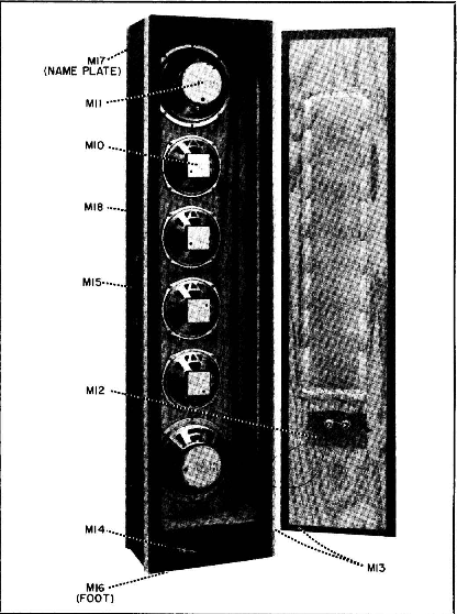
        The old 60īs PA columns , think what he Beatles used, or what was found in a Church, often had a long slot in the back, usually somewhat covered by thick cloth or fiberglass, hereīs a Shure Vocal Master column and the slot in the back, although covered, is clearly marked:

        Surprise !!!!! ... the Shure Vocal Master amplfier driving these columns was Constant Current Drive !!!!!!
        NOT milder mixed feedback but the real deal.
        No doubt it gave those columns needed extra bass but specially extended treble for voice clarity and definition, they used no tweeters but plain guitar type 8" and 10" speakers,gthey could definitely use some 6 to 10 dB boost at high frequencies.

        Thatīs why I am quite certain your Line 6 open back cabinet provides some lossy damping to your speaker.
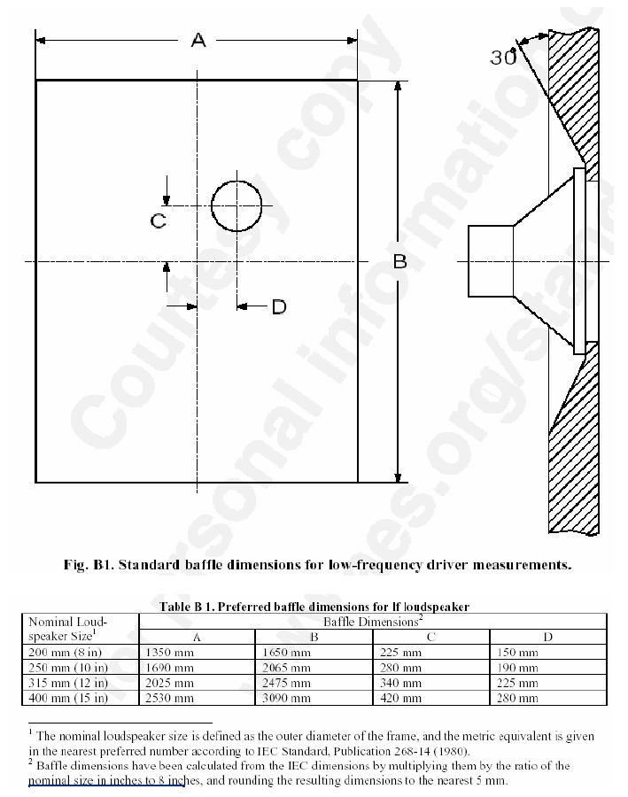
        Standard anechoic chamber tests usually take 2 forms: some just hang the bare speaker from a hook , which in theory is the "more honest" way, although nobody will use it that way, while most use some kind of generic "flat piece of plywood" baffle.

        IEC baffle:


        practical use:


        both systems let the speaker fully undamped, any realistic baffle will damp resonances, even if a little.
        Juan Manuel Fahey

        Comment


        • #34
          Originally posted by benito_red View Post
          agree that proper preamp EQ can be an alternative to hi-out-Z.

          You mentioned SS without feedback. AFAIK nobody never built such amp, but it would provide not only hi-out-Z but likely soft-clipping as well. The only way I know to do that would be
          to use the same tube topology: power transistors coupled to the load thru out-transformer. Do you know a different way and eventually share your findings (if it is not a secret)?
          Not a secret at all... posts 31 and 32 describe some of the options. I have spent some time pursuing an approach described here...
          https://sites.google.com/site/string...m-lite-project

          The power amp uses no global feedback - I've used numerous "follower circuits" (transistor, tube, or mosfet), and each does have it's local feedback stabilization, but that doesn't impact OD in general since there is no gain in follower stages. As already mentioned, OD tone has many other dimensions beyond freq response - I'm only making the point that a SS output (LoZ, voltage source) can mimic freq response due of tube (HiZ, current source) speaker drive without use of Current Feedback. There is an alternative to current feedback if you don't like the OD character it produces.
          “If you have integrity, nothing else matters. If you don't have integrity, nothing else matters.”
          -Alan K. Simpson, U.S. Senator, Wyoming, 1979-97

          Hofstadter's Law: It always takes longer than you expect, even when you take into account Hofstadter's Law.

          https://sites.google.com/site/stringsandfrets/

          Comment


          • #35
            Originally posted by benito_red View Post
            You mentioned SS without feedback. AFAIK nobody never built such amp, but it would provide not only hi-out-Z but likely soft-clipping as well. The only way I know to do that would be
            to use the same tube topology: power transistors coupled to the load thru out-transformer. Do you know a different way and eventually share your findings (if it is not a secret)?
            The first attachment is a simple design with no global AC feedback. Output impedance depends on the beta of the output transistors and the 2.2K resistors in the driver bootstrap. The one I build measured 5 Ohms calculated from small signal output into 4 and 8 Ohms. Voltage gain is set by the source resistor of the driver MOSFET and the resistors in the bootstrap.

            The second attachment is from an old version of the Randall RG100ES. Note that C34 bypasses all the Voltage feedback (it sets the DC output Voltage) and all AC feedback comes from the current sense resistor R63 via C36 and R52. Might be a little unstable with no load.
            Attached Files
            WARNING! Musical Instrument amplifiers contain lethal voltages and can retain them even when unplugged. Refer service to qualified personnel.
            REMEMBER: Everybody knows that smokin' ain't allowed in school !

            Comment


            • #36
              Originally posted by loudthud View Post
              The first attachment ..... Might be a little unstable with no load.
              that is very interesting, Thanks to LOUDTHUD for the schematics, I suppose it needs to select power transistors in order to have beta as close as possible.
              Thanks to all people that took part in this topic

              Comment

              Working...
              X