Ad Widget

Collapse

Announcement

Collapse
No announcement yet.

How the TMB Tone Stack Works Webpage

Collapse
X
 
  • Filter
  • Time
  • Show
Clear All
new posts

  • How the TMB Tone Stack Works Webpage

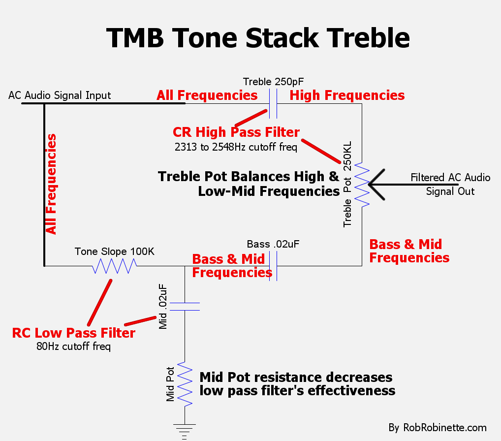
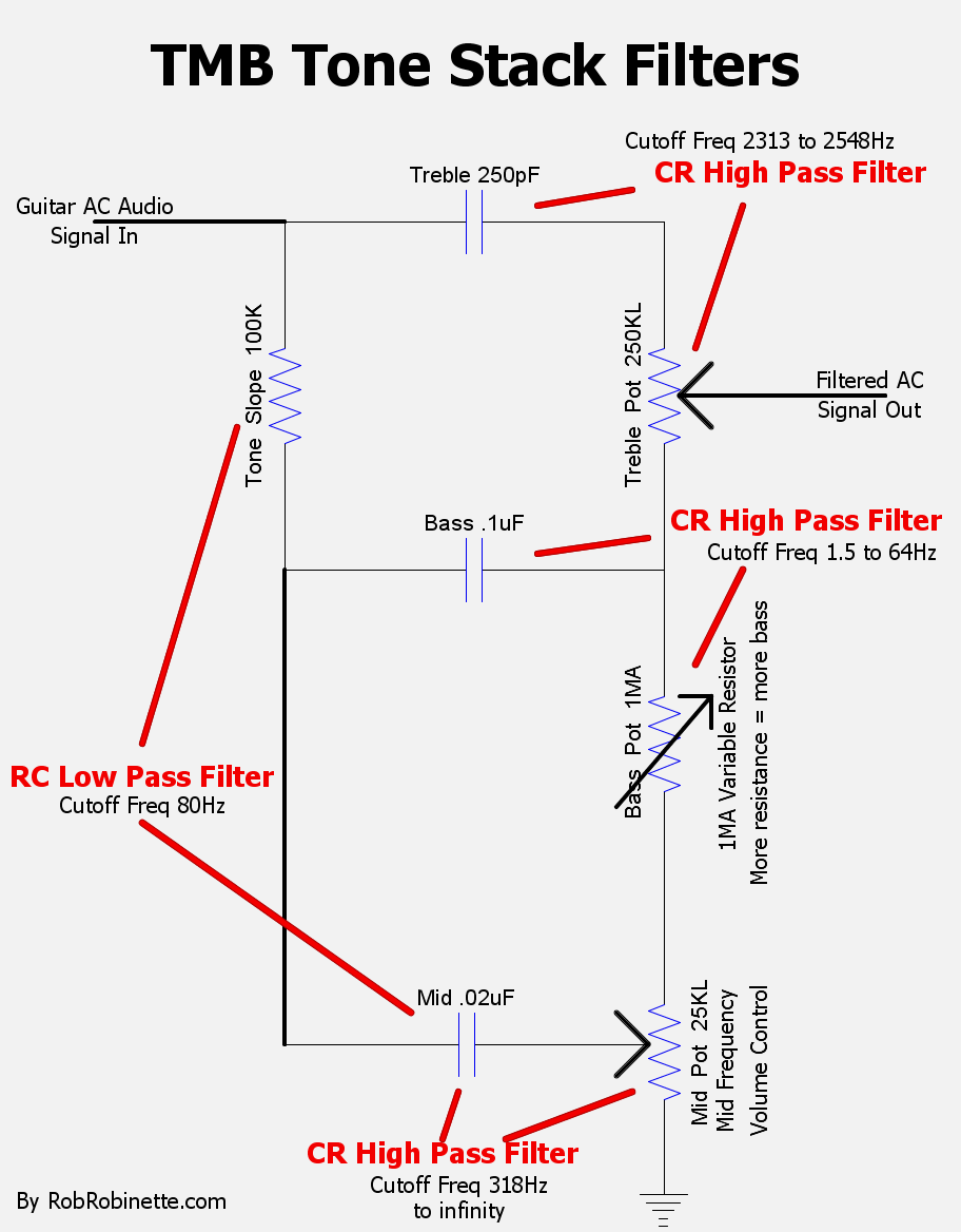
    I'm working on a How the TMB Tone Stack Works webpage and I'm stretching at the limits of my knowledge and understanding of audio circuits. I know many of the sharpest tube amp audio minds in the world hang out here so I'm asking if you could review the webpage for accuracy and suggestions before I release it into the wild. Thank you in advance.

    Sample graphics:


    https://RobRobinette.com/Amp_Stuff.htm

  • #2
    Hi. This is most important remark regards tone stack ever read. Take it in consideration
    Originally posted by Gingertube View Post
    I think the point of my post above was missed.
    The Duncan TSC just tells you what the tone stack does in isolation from the driving stage - yes you can give it different source impedances to see what happens but that still doesn't explain the drive stage/ tone stack interaction for an anode drive stack.

    Say you want a mid cut function. You set the tone stack pots to give that, the tone stack impedance to 0V will be low at those mid frequencies (shunting more of the mids to 0V).
    That lower impedance is in parallel with the anode load resistor which will lower the gain at those mid frequencies.
    That is, the driving stage will produce less signal at those frequencies to begin with and then that reduced signal will be cut again by the tone stack.
    OR
    Say you want a treble boost, the tone stack impedance to 0V will then be higher at those treble frequencies (less treble shunted to 0V).
    The anode load resistor in parallel with that impedance will be higher and the driving stage gain will be higher at those frequencies, producing more of those frequencies and then less of them will be shunted to 0V.
    So the tone stack and its driving stage together will have a larger range of control.

    This effect is dependent upon the impedances. With the very low output impedance from a cathode follower you do not get this tone stack + driving stage interaction. The tone stack is "isolated" from its driving stage.

    Another useful (but not completely accurate) way of thinking about the anode driven stage + tone stack is that the source impedance into the tone stack is not constant but varies with frequency according to where you set the tone stack pots. The Duncan TSC doesn't allow you to model that.

    Cheers,
    Ian

    P.S. Whenever you use a simulator it is important to understand what it is NOT going to tell you as is to understand what it is going to tell you.
    This can often be worked out by examining the basic assumptions the simulator works with.
    For the Duncan Tone Stack Simulator it assumes 2 things:
    A flat frequency response driver and a source impedance which is flat with frequency.
    In the case of the anode driven tone stack, neither of these assumptions are true. Both are modified by the impedance to 0V vs frequency characteristic of the tone stack itself.
    "If it measures good and sounds bad, it is bad. If it measures bad and sounds good, you are measuring the wrong things."

    Comment


    • #3
      Thanks catlin, that's good info on the driving stage to tone stack interaction.
      https://RobRobinette.com/Amp_Stuff.htm

      Comment


      • #4
        I think that in their usual implementations, the Fender BF and Marshall tonestacks appear to offer an adequate impedance bridge type of load to their drivers, hence output variation due to the loading effects resulting from the particular control settings shouldn't affect the response etc excessively.
        And over the relevant bandwidth, the response of the driver stages against frequency seems sufficiently flat to be ignored.
        Hence the TSC assumptions seem reasonable to me?

        An impedance bridge being intended for good signal voltage transfer, ideally load impedance >=10 x source impedance, with a reasonable bridge being formed by a load ~3 x source impedance.
        Last edited by pdf64; 01-18-2017, 12:09 PM.
        My band:- http://www.youtube.com/user/RedwingBand

        Comment


        • #5
          Originally posted by pdf64 View Post
          An impedance bridge being intended for good signal voltage transfer, ideally load impedance >=10 x source impedance, with a reasonable bridge being formed by a load ~3 x source impedance.
          I haven't read that before, but seems like a good thumbrule. So if the driving stage plate Z is about 50k (a scoshe higher than typical but chosen to make the math easier) and the driven grid Z is 1M then we're OK there, 10x with a factor of 2x for wiggle room. The tone stack (bridge circuit) should have a Z for all frequencies of interest between about 150k [actually since sqrt(10) = 3.16 it should be ~ 158k] and about 300k (316k). I know I've calculated tone stacks with a much lower composite Z, but there's probably a tradeoff between loading and noise.

          Is that the kind of circuit analysis that you had in mind?
          If it still won't get loud enough, it's probably broken. - Steve Conner
          If the thing works, stop fixing it. - Enzo
          We need more chaos in music, in art... I'm here to make it. - Justin Thomas
          MANY things in human experience can be easily differentiated, yet *impossible* to express as a measurement. - Juan Fahey

          Comment


          • #6
            Yes, that's pretty much it.
            To keep things simple, with the regular tone stack, I just think of the worst case load on the driver stage as being a bit less than the slope resistor.

            I find that a regular 12AX7 CC stage works well down to a load of ~100k.
            Much below that and I think the tone seems to suffer somehow.
            I acknowledge that means every Fender opto trem channel (having a 50k trem intensity pot as the load on their last pre-amp stage) has room for improvement, but it's simple enough for anyone with a mind to tweak these things to check out for themselves.
            I like to use a 100k lin pot for trem intensity, which (to me) noticeably improves things.

            By the same token, I'm not keen on using the 5F6A tone stack with a CC driver, as the 56k slope resistor may tend to present too heavy a load.
            My band:- http://www.youtube.com/user/RedwingBand

            Comment

            Working...
            X