Ad Widget

Collapse

Announcement

Collapse
No announcement yet.

Modular tube preamp idea, crazy?

Collapse
X
 
  • Filter
  • Time
  • Show
Clear All
new posts

  • Modular tube preamp idea, crazy?

    It's been a while since I last built anything, but now I've got this idea I just can't let go of:

    A modular tube preamp, that contains tube gain stages in one box, and all tone controls (i.e. stuff that operates linearly, not only user-adjustable controls) in another, probably op-amp based box. This way I could build the expensive high-voltage stuff once, and try out different ideas, by plugging in circuitry feeding the gain stages with different signals. I could switch between different circuits and possibly even make a MIDI controlled version, using digital pots.

    Looking at what makes tube pre-amp tone, there seems to be two crucial circuits: The basic triode gain stage, and the dc-coupled cathode follower. My idea was to put two triode gain stages, both followed by a clean ac-coupled cathode follower (for low output impedance), and two dc-coupled cathode followers in the "tube box", and simply provide in and out jacks for each of the four. You could then hook up the "tone box", which would implement various fixed filters, gain control(s), a tone stack, and a master volume.

    Main concerns/questions I have:
    1. Will I have issues with noise or stability if I have this stuff in two boxes like this?
    2. Would using send-syle TRS connections between each gain stage work, or do I really need to plug 8 cables between the boxes to make it work optimally? These would be just short patch cables. Or is there some multi-poled connector that would work well for this?
    3. Did I miss something else crucial, which would make this a stupid idea?
    4. What would be the best way to make bias adjustable? Just carry a dc voltage in the signal, or put e.g. relay-controlled cathode resistors in the tube box?
    5. I think I would be able to model any rather basic preamp with this, by just doing filtering in the "tone box". Of course it wouldn't be 100% identical to the original circuit, but very close. Or am I missing something?

    Any feedback or idea is very welcome!
  • #2
    Well, if you really wanted to freak everybody out, you could use banana jacks.
    If I have a 50% chance of guessing the right answer, I guess wrong 80% of the time.

    Comment


    • #3
      This is from one of my custom designs I did to keep tube count low and satisfy a customer request. It's a whole amp with bias trem and reverb, but the preamp design and tone stack allocations might interest you for your project. Two preamp tubes and switches between "American" and "British" topologies using the same panel arrangement.
      Attached Files
      Last edited by Chuck H; 01-23-2017, 12:42 AM.
      "Take two placebos, works twice as well." Enzo

      "Now get off my lawn with your silicooties and boom-chucka speakers and computers masquerading as amplifiers" Justin Thomas

      "If you're not interested in opinions and the experience of others, why even start a thread?
      You can't just expect consent." Helmholtz

      Comment


      • #4
        Look up the Seymour Duncan COnvertible 100 amp. They did the preamp molules 25 years ago. You could choose from a variety of modules for gain, overdrive, clean, whatever.
        Education is what you're left with after you have forgotten what you have learned.

        Comment


        • #5
          Randall developed 20-30 years ago some sort of amp series with modular slot preamps. The modules like slots with faceplates contained all interface need it ( tone stack, switches etc.) I don.t remember what model was but sound pretty fair on era. dig it!
          "If it measures good and sounds bad, it is bad. If it measures bad and sounds good, you are measuring the wrong things."

          Comment


          • #6
            A friend of mine blew up his SD convertible and gave me the carcass, so I've looked at their modules is some detail. Simple options, really, like cathode bypass cap or not, different anode resistor values, higher or lower or frequency-specific loading on the grid. But a good idea. In this case the high voltage stayed in the amp chassis, and the tube modules plugged in with edge connectors sort of like computer cards.

            For a tube stage - linear IC interface to work, you'll need to specify what signal level is acceptable at the patch cord layer. While +4dB (pro sound gear level) is a couple volts AC, the output of a preamp tube driven to distortion can be 100VAC or more, depending on the B+ at the tube anode. Amps that have an FX loop have to deal with this level matching.

            I've seen a few threads on MEF from designers who have laid their amps out 'breadboard style' so component and circuit changes can be made with relative ease. You may get some ideas from pictures of their efforts.
            If it still won't get loud enough, it's probably broken. - Steve Conner
            If the thing works, stop fixing it. - Enzo
            We need more chaos in music, in art... I'm here to make it. - Justin Thomas
            MANY things in human experience can be easily differentiated, yet *impossible* to express as a measurement. - Juan Fahey

            Comment


            • #7
              I believe Bruce Egnater was one of the first with a modular preamp, with his Natec version
              Click image for larger version

Name:	natec002.jpg
Views:	1
Size:	104.1 KB
ID:	844608
              reportedly only two were made, followed later by Egnater, Randall and Rocktron versions

              Comment


              • #8
                I've seen such projects on the internet so the idea is great but slightly to late.

                Comment


                • #9
                  The general idea is good, but I think it would be difficult to make it work for anything else than breadboarding. To get something workable for gigs or band practice, I think a better idea to make a base module with a power supply, switching and so on. Then buid the different preamps as modules containing all tubes, tone controls, etc for the preamp.
                  To make each module more flexible, you could use trimpots or switches to select different components.

                  The most tricky bit will be to ensure that the connentors for the high-voltage supply is safe and does not risk causing shock or fire if it's damaged or accidentally unplugged.

                  Comment


                  • #10
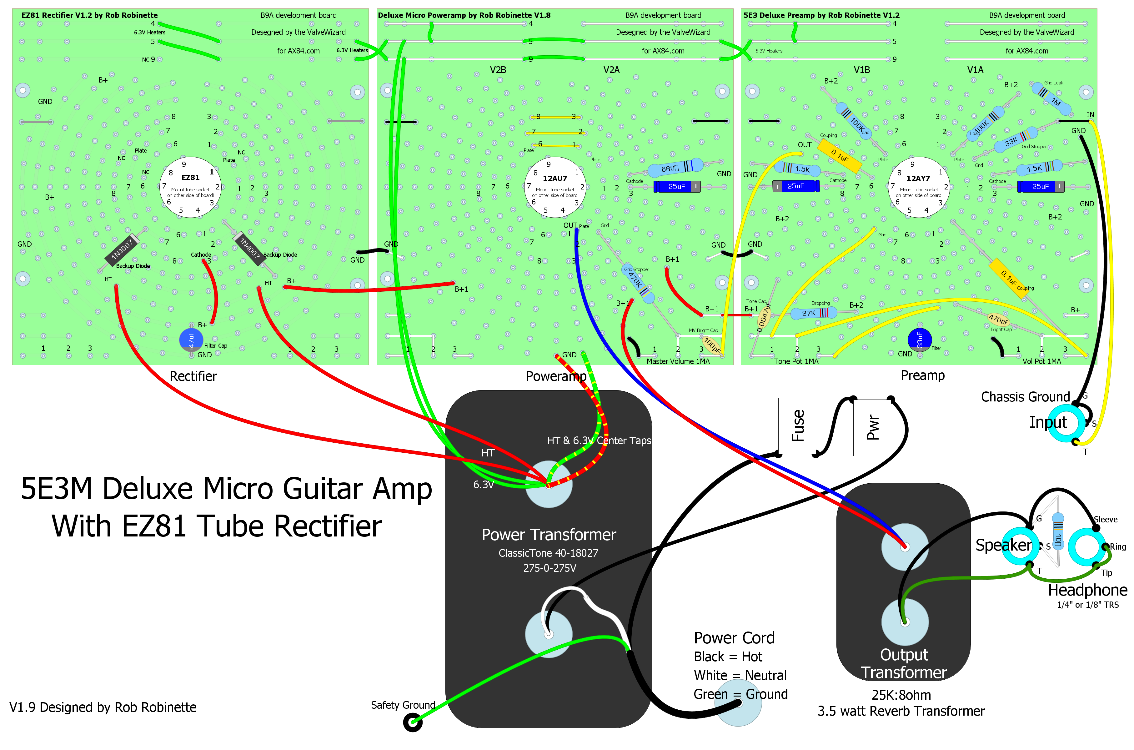
                    Merlin Blencowe made these cool little 9 pin tube socket PCB B9A circuit boards that you can use to stitch together tube amp circuits. You can mix-and-match some cool amp experiments.

                    https://robrobinette.com/ValveWizard...ment_board.htm

                    On the left is the tube rectifier circuit (with safety backup diodes), center is the power amp and the preamp is on the right.
                    Last edited by robrob; 01-23-2017, 12:40 PM.
                    https://RobRobinette.com/Amp_Stuff.htm

                    Comment


                    • #11
                      No, not crazy at all.
                      In different ways it can and has been done.
                      Because of practical reasons, if you want to make some parts plug-in switchable, make the tubes/HV/filaments parts fixed and tone controls and such plug-in.

                      Originally posted by sbergen View Post
                      It's been a while since I last built anything, but now I've got this idea I just can't let go of:

                      A modular tube preamp, that contains tube gain stages in one box, and all tone controls (i.e. stuff that operates linearly, not only user-adjustable controls) in another,
                      That.
                      probably op-amp based box.
                      As said above, Op Amps work with 30V supplies, tubes with 300V ones, so tube signal levels are typically 10X larger than the *maximum* that Op Amps can stand.
                      Heavy padding must be used for interfacing, and then at least 10X gain with suitable devices (high voltage Fets?) must be added at *each* interface point so signals recover original levels.
                      It can be done, of course, but it sure complicates things.
                      This way I could build the expensive high-voltage stuff once,
                      oh, itīs not that expnsive.
                      A 12AX7 typically costs around U$10/12 while 4 pots and knobs (say: volume, treble, mid, bass) cost some U$8 , , if you add needed connectors plus passive parts you end up spending same as on tubes or more.


                      and try out different ideas, by plugging in circuitry feeding the gain stages with different signals. I could switch between different circuits
                      cool
                      and possibly even make a MIDI controlled version, using digital pots.
                      can be done, is not easy, and you have to solve the level matching problems.
                      Looking at what makes tube pre-amp tone, there seems to be two crucial circuits: The basic triode gain stage, and the dc-coupled cathode follower. My idea was to put two triode gain stages, both followed by a clean ac-coupled cathode follower (for low output impedance), and two dc-coupled cathode followers in the "tube box",
                      cool
                      and simply provide in and out jacks for each of the four. You could then hook up the "tone box", which would implement various fixed filters, gain control(s), a tone stack, and a master volume.
                      it could work.
                      Youīll soon look like a 40`s phone operator though


                      Main concerns/questions I have:
                      1. Will I have issues with noise or stability if I have this stuff in two boxes like this?
                      Noise? Not if you are careful about shielding and grounding.
                      Stability?
                      Maybe.
                      High gain circuits do not like long wiring, often more than 1 or 2 inches can bring problems.
                      2. Would using send-syle TRS connections between each gain stage work, or do I really need to plug 8 cables between the boxes to make it work optimally? These would be just short patch cables. Or is there some multi-poled connector that would work well for this?
                      Depending on what you want to connect, TRS will not be enough, all modular premps use multi pin connectors , you might need to connect , say, 8 to 16 wires.
                      3. Did I miss something else crucial, which would make this a stupid idea?
                      No, the idea is cool.
                      Just the practical implementation might be somewhat more complex or expensive than you first envisioned.
                      Just try it
                      4. What would be the best way to make bias adjustable? Just carry a dc voltage in the signal, or put e.g. relay-controlled cathode resistors in the tube box?
                      Separate bias and signal.
                      Otherwise when plugging/unplugging you will have HUGE thumps, momentarily leave tubes unbiased, etc. All BAD things.
                      5. I think I would be able to model any rather basic preamp with this, by just doing filtering in the "tone box". Of course it wouldn't be 100% identical to the original circuit, but very close. Or am I missing something?
                      You can build it as simple or complex as you wish, itīs your time and project
                      Juan Manuel Fahey

                      Comment


                      • #12
                        [QUOTE=J M Fahey;445649]
                        it could work.
                        Youīll soon look like a 40`s phone operator though
                        p[QUOTE]

                        COOL!!!!!!!

                        Screw a wall of stacks. Do like Neil Young did on the Rust Never Sleeps tour, with an army of minions coming out to switch all your phone plugs manually between shows. Or Geddy and his chefs and housekeepers coming out to baste the chickens and switch over the laundry.

                        Justin
                        "Wow it's red! That doesn't look like the standard Marshall red. It's more like hooker lipstick/clown nose/poodle pecker red." - Chuck H. -
                        "Of course that means playing **LOUD** , best but useless solution to modern sissy snowflake players." - J.M. Fahey -
                        "All I ever managed to do with that amp was... kill small rodents within a 50 yard radius of my practice building." - Tone Meister -

                        Comment


                        • #13
                          Originally posted by MarkusBass View Post
                          I've seen such projects on the internet so the idea is great but slightly to late.
                          I wasn't able to find any where the idea is to put gain stages in one module, and everything else in another. If you have any links, I'd be interested in reading other's experiences!

                          Comment


                          • #14
                            Originally posted by d95err View Post
                            The most tricky bit will be to ensure that the connentors for the high-voltage supply is safe and does not risk causing shock or fire if it's damaged or accidentally unplugged.
                            Yeah, I thought about it also, but this is what turned me off.

                            Comment


                            • #15
                              Originally posted by J M Fahey View Post
                              As said above, Op Amps work with 30V supplies, tubes with 300V ones, so tube signal levels are typically 10X larger than the *maximum* that Op Amps can stand.
                              Heavy padding must be used for interfacing, and then at least 10X gain with suitable devices (high voltage Fets?) must be added at *each* interface point so signals recover original levels.
                              If I'm considering preamp stages only, and limit each stage to work with a simple triode gain stage in front, the input wouldn't need to swing more than five volts. As for the output, I'd probably scale it to be around line level when leaving the tube module.

                              Originally posted by J M Fahey View Post
                              Stability?
                              Maybe.
                              High gain circuits do not like long wiring, often more than 1 or 2 inches can bring problems.
                              Can someone point me at why this is? If all stages have low-impedance outputs, are they still susceptible to this?

                              Originally posted by J M Fahey View Post
                              Depending on what you want to connect, TRS will not be enough, all modular premps use multi pin connectors , you might need to connect , say, 8 to 16 wires.
                              One TRS cable per gain stage for the signal was my thought. If etc. bias is handled separately, I'd probably put that through some separate control signal.

                              Originally posted by J M Fahey View Post
                              Separate bias and signal.
                              Otherwise when plugging/unplugging you will have HUGE thumps, momentarily leave tubes unbiased, etc. All BAD things.
                              Good point!

                              Originally posted by J M Fahey View Post
                              You can build it as simple or complex as you wish, itīs your time and project
                              I started thinking maybe four stages is overkill, I could probably do plenty with two also. Perhaps three

                              Comment

                              Working...
                              X