Ad Widget

Collapse

Announcement

Collapse
No announcement yet.

Please Check My Filter Theory

Collapse
X
 
  • Filter
  • Time
  • Show
Clear All
new posts

  • Please Check My Filter Theory

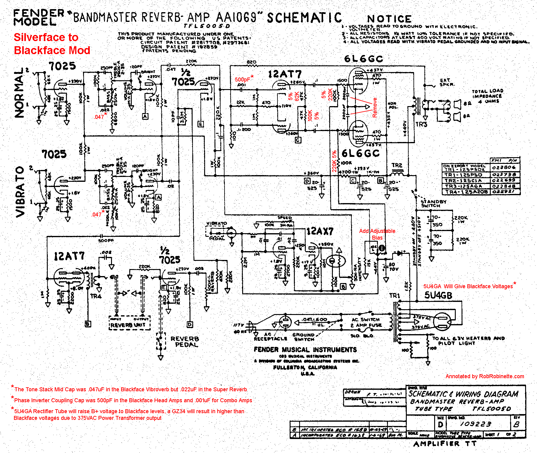
    I want to add reverb & tremolo to a silverface amp's normal channel using the method Fender used in the 68 Custom Deluxe Reverb. Fender joined the 2nd stage preamp plates together and eliminated the Normal channel's .047uF coupling cap to add the FX to the Normal channel.

    I typically use the Normal channel's coupling cap as part of a "lead channel mod" to trim some bass by dropping it to a .0022uF. Since that option isn't available with the reverb mod I want to add a .0022uF cap after the Normal channel input circuit's two 68k grid stopper resistors. I will move the 1M grid leak to between the new cap and 1st stage grid.

    I've crunched the numbers and it looks like the .0022uF + 1M grid leak's CR high pass filter will do what I want. Does anyone see a problem with this method?

    Thanks in advance for the help.
    https://RobRobinette.com/Amp_Stuff.htm

  • #2
    Originally posted by robrob View Post
    I typically use the Normal channel's coupling cap as part of a "lead channel mod" to trim some bass by dropping it to a .0022uF. Since that option isn't available with the reverb mod I want to add a .0022uF cap after the Normal channel input circuit's two 68k grid stopper resistors. I will move the 1M grid leak to between the new cap and 1st stage grid.

    I've crunched the numbers and it looks like the .0022uF + 1M grid leak's CR high pass filter will do what I want. Does anyone see a problem with this method?
    Should work OK but how about something a little easier: reduce the bypass cap on that preamp's cathode resistor to say 2 uF?

    Also, I'm not in favor of glomming together (Y-cording) plates that way. Your signal doesn't only go in the "forward" direction you may want it to, signal goes both ways & one plate sinks signal from the other. There's a reason mixers use resistors, to isolate the unwanted effects of the preamp outputs. I find it hard to believe they did that, but . . . there they go. Again. A pair of 220K would fix Fender's cheapo "solution".
    This isn't the future I signed up for.

    Comment


    • #3
      Thanks Leo, the "lead channel mod" already uses a .68uF cathode bypass cap on the Normal channel first stage preamp.

      I don't want to mod the Vibrato channel but I could add one 220k mixing resistor after the .0022uF coupling cap and the Vibrato channel plate. Would that be worth adding and would that add any unintended consequences?
      https://RobRobinette.com/Amp_Stuff.htm

      Comment


      • #4
        Originally posted by robrob View Post
        I don't want to mod the Vibrato channel but I could add one 220k mixing resistor
        I can't quite visualise your circuit but if there's only one mixing resistor then the other mixing resistor is the output impedance of the other tube's plate which is about 35k (I think) so the output from the tube with the 220k resistor is attenuated by about 7 times (17dB). With two mixing resistors the attenuation is only 2 (6dB).
        Last edited by Dave H; 03-28-2017, 06:39 PM.

        Comment


        • #5
          Hi.if you filter teory means tone shaping in a way to control bass reponse both methods mentioned are effective. But I have to add one more: interstage impedance bridging
          "If it measures good and sounds bad, it is bad. If it measures bad and sounds good, you are measuring the wrong things."

          Comment


          • #6
            Originally posted by robrob View Post
            Thanks Leo, the "lead channel mod" already uses a .68uF cathode bypass cap on the Normal channel first stage preamp.
            Dad-blang-it they beat me to the punch... oh well!
            This isn't the future I signed up for.

            Comment


            • #7
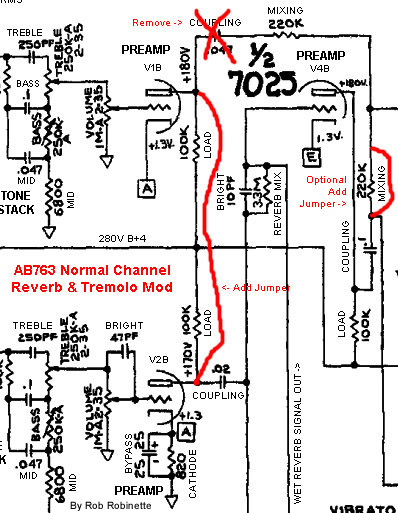
              This is my unmodified amp:


              This the mod Fender used with the 68 CDR to add FX to the normal channel. The single 220k mixing resistor would be inserted into the red jumper:

              https://RobRobinette.com/Amp_Stuff.htm

              Comment


              • #8
                Thanks for the schematics.

                Adding the link will work. It reduces the voltage swing available because of the low loading but that must be OK as Fender did it. I think replacing the link with a 220k will result in the top channel having less gain (17dB?) than the bottom channel. Anyway it's easy enough to try it both ways.

                Another way to do it would be to have two mixing resistors and two coupling caps then you could fine tune the bass differently for both channels without having to modify the Normal channel front end. Looking at the unmodified schematic I can see that that's how the channels were mixed at the PI input before the mod.
                Last edited by Dave H; 03-29-2017, 10:30 AM.

                Comment


                • #9
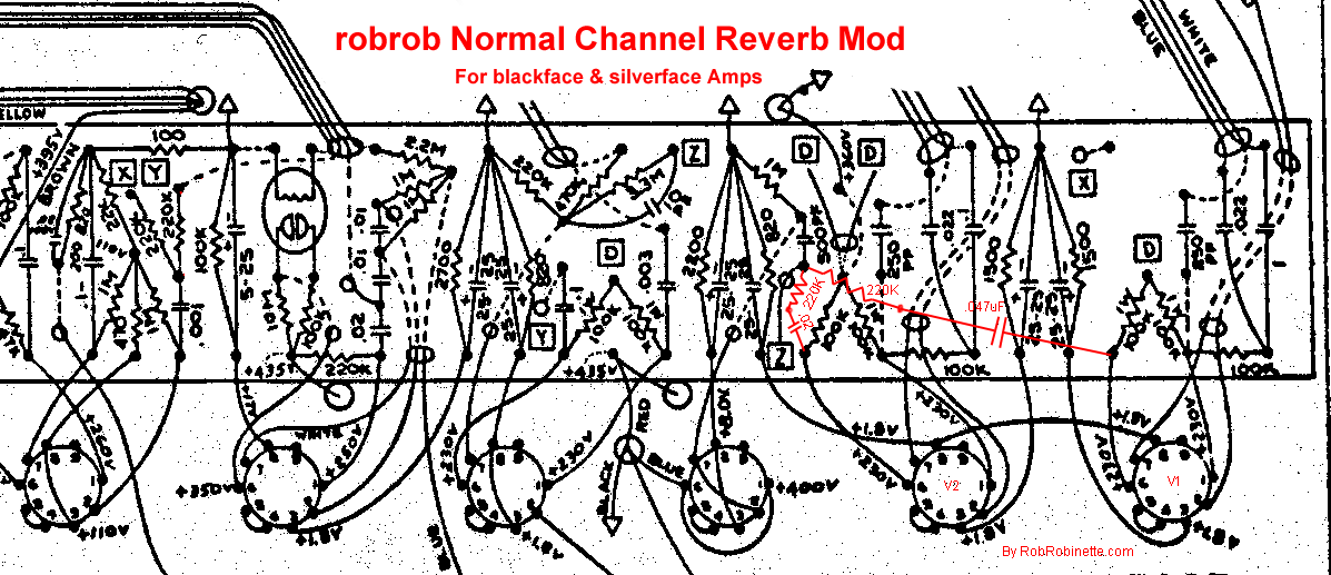
                  Thanks Dave, I had considered joining the two channels with coupling caps and 220k mixing resistors but it seemed too invasive. After reconsidering I believe I can join the two channels with their own coupling caps and mixing resistors in a relatively noninvasive way.

                  Insert a new 220k mixing resistor at the Vibrato channel V2B coupling cap: pull the coupling cap output end loose and bend it upwards, then tie the loose end to the empty eyelet with a 220k resistor.

                  Remove the Normal channel's .047 cap.

                  Solder a .0022uF coupling cap in its place but only solder a lead to the input eyelet.

                  Bend the new cap's leads towards the Vibrato channel's new mixing resistor.

                  Use a 220k mixing resistor to tie the new Normal channel coupling cap to the output end of the Vibrato channel's new mixing resistor.

                  Jumper around the now unneeded original Vibrato channel mixing resistor.
                  https://RobRobinette.com/Amp_Stuff.htm

                  Comment


                  • #10
                    Here's the mod shown on a silverface layout showing the stock value coupling caps. The mod is the same for blackface amps:

                    Last edited by robrob; 03-29-2017, 04:31 PM.
                    https://RobRobinette.com/Amp_Stuff.htm

                    Comment


                    • #11
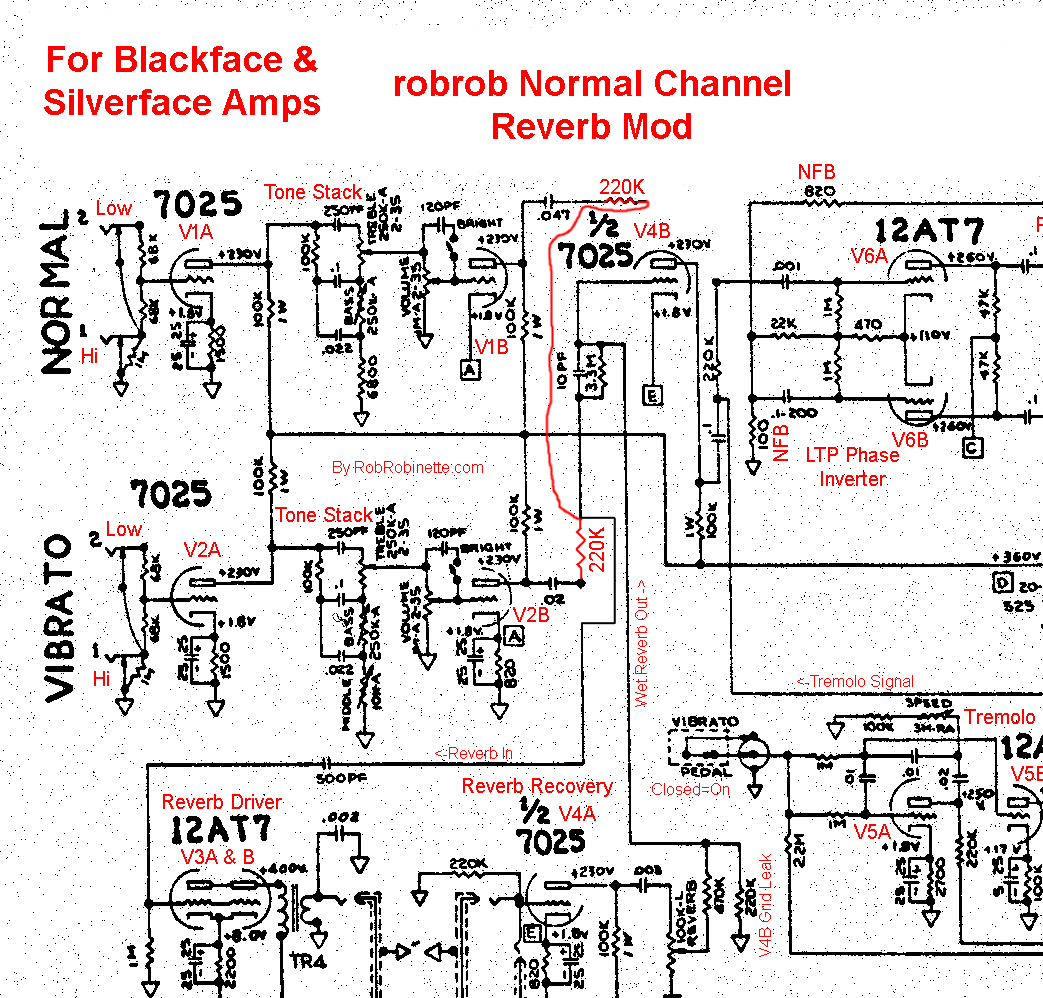
                      Here's the schematic for the mod:

                      https://RobRobinette.com/Amp_Stuff.htm

                      Comment


                      • #12
                        Originally posted by robrob View Post
                        Here's the schematic for the mod:
                        Yep, now that looks like the mod I've been doing. With the Norm channel typically changed to a sort of 5F6A tweed Bassman preamp. It's also handy to have that V4B grid leak R, you can alter its value to bump the overall gain up or down a bit.
                        This isn't the future I signed up for.

                        Comment


                        • #13
                          There may be some problems with the resistive mixer scheme. When the Normal plate and the Vibrato plate both have the same signal at the same magnitude, then each plate looks like a very high impedance to the other plate. If one plate has no signal, then it looks like a very low impedance to the other plate. If one plate has something between no signal and a signal equal to the other plate, then it looks like an impedance somewhere between very low and very high to the other plate.

                          If you strap the channels, the Vibrato channel will become quieter as the Normal channel is decreased because the Normal plate looks like a lower impedance which alters the voltage divider for the Vibrato plate.

                          When the Vibrato plate sees a low impedance from the Normal plate, the .0022uF capacitor makes this impedance higher at lower frequencies. This will cause the Vibrato channel to have more bass as the Normal channel is turned down.

                          Comment


                          • #14
                            If you want reverb on the Normal channel (as stated in the OP) then I don't think that circuit will do it because the Normal channel isn't driving the Reverb in directly as the Vibrato channel does. The Normal channel has the two mixing resistors between its output and Reverb in. Perhaps it would work if you moved the Reverb in connection to the junction of the 220k mixing resistors and 3M3?

                            Comment


                            • #15
                              Originally posted by Dave H View Post
                              Perhaps it would work if you moved the Reverb in connection to the junction of the 220k mixing resistors and 3M3?
                              Yes, that's right.
                              This isn't the future I signed up for.

                              Comment

                              Working...
                              X