Hi all,
I open this thread because I would like to talk about phase inverters with constant current sinks. Few designs apply them in the guitar world, and I think there can be more to squeeze from it with the partecipation of all of us.
I've recently bought a Marshall 9200, and I re-jumped in the PIs with CCS world were I've been years ago with the Mesa Boogie 295 Simul Class.
While fixing some weak points of the 9200 project (mainly bias and NPN for the CCS), I've done some simulations on the possibility to do some small improvements on the design of the PI.
Well, the advantage of the CCS is (close to) infinite AC impedance (good for PI balance) while DC current flows as per the circuit setup. In the case of the Marshall 9200 circuit, the current is:
0,7 V / 270 Ohm = 2,6 mA
The concept is the same described here:

Practical Phase Inverters.
This configuration has in fact very low distortion, with a bit of a prevalence of 3rd harmonic.
By looking at this other configuration by Crowhurst:

https://archive.org/stream/Crowhurst...sic_3_djvu.txt
So I came out with this simple modification on the 9200 to apply the following:
- center the plates of the PI at 2/3 of B+
- increase the current capabilities of the PI
- apply some positive feedback between input stage and PI
- give more dynamic range to the PI
Anyone has some experience on them, from direct design or as a user of one amp with this configuration?
I open this thread because I would like to talk about phase inverters with constant current sinks. Few designs apply them in the guitar world, and I think there can be more to squeeze from it with the partecipation of all of us.
I've recently bought a Marshall 9200, and I re-jumped in the PIs with CCS world were I've been years ago with the Mesa Boogie 295 Simul Class.
While fixing some weak points of the 9200 project (mainly bias and NPN for the CCS), I've done some simulations on the possibility to do some small improvements on the design of the PI.
Well, the advantage of the CCS is (close to) infinite AC impedance (good for PI balance) while DC current flows as per the circuit setup. In the case of the Marshall 9200 circuit, the current is:
0,7 V / 270 Ohm = 2,6 mA
The concept is the same described here:

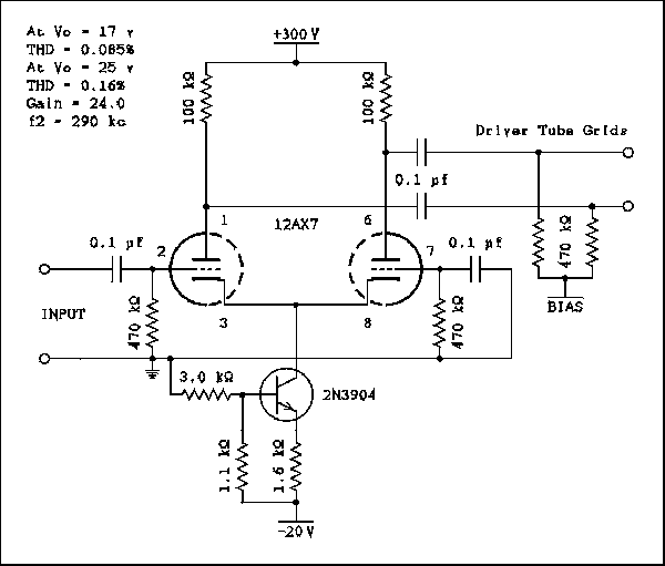
Lets say the collector current tries to increase. The emitter current will also try to increase which makes the drop across the 1.6 k ohm resistor increase. Because the base voltage is held very constant by the voltage divider of the 3 k and 1.1 k ohm resistors the bias on the base-emitter junction will be decreased. This will decrease the base current and cancel out most of the collector current increase. The collector current has to change by a small amount to make the base current change, but the change is very small. The collector current is 3 mA and most 3904s have a current gain of more than 100 so the base current is about, or less than, 30 microamps. The divider current is 4.88 mA. The base current is 0.615% of the divider current.
As you can see the distortion was very low, much lower than I had expected. Also the distortion at both outputs was very similar. When feedback was simulated the balance remained perfect. The distortion changed though. The plate on the left gave 0.09% while the right hand plate gave 0.175%. This low level of distortion means the distortion imbalance can be disregarded.
As you can see the distortion was very low, much lower than I had expected. Also the distortion at both outputs was very similar. When feedback was simulated the balance remained perfect. The distortion changed though. The plate on the left gave 0.09% while the right hand plate gave 0.175%. This low level of distortion means the distortion imbalance can be disregarded.
This configuration has in fact very low distortion, with a bit of a prevalence of 3rd harmonic.
By looking at this other configuration by Crowhurst:

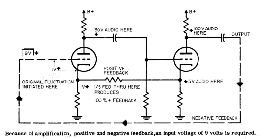
Positive feedback can only be used over one stage in order to avoid oscil-
lation. An easy way to accomplish this positive feedback is to couple cathode
bias resistors of two consecutive stages in the earlier part of the amplifier,
where the distortion is small.
A momentary positive fluctuation at the grid of the first stage will pro-
duce a momentary negative fluctuation at the plate, which is passed on to
the grid of the following stage. This produces another positive fluctuation
at the plate of the second tube. At the same time, the negative fluctuation
at the plate of the first tube, resulting from increased plate current, will be
accompanied by a positive fluctuation at its cathode. Similarly, a negative
fluctuation appears at the cathode of the second tube. The fluctuation at
the cathode of the second tube is much bigger than that at the first stage.
Connecting the resistor between the cathodes will allow some of the fluctua-
tion from the cathode of the second stage to cancel the fluctuation at the
cathode of the first stage.
So I came out with this simple modification on the 9200 to apply the following:
- center the plates of the PI at 2/3 of B+
- increase the current capabilities of the PI
- apply some positive feedback between input stage and PI
- give more dynamic range to the PI
Anyone has some experience on them, from direct design or as a user of one amp with this configuration?
Comment