Ad Widget

Collapse

Announcement

Collapse
No announcement yet.

relay wiring

Collapse
X
 
  • Filter
  • Time
  • Show
Clear All
new posts

  • relay wiring

    Hello all,

    I have a quick question about relay wiring.

    If i want to activate the relay with at the same time turning on the LED, I need to simultaneously ground the negative side of the relay coil as well as ground the LED (Being fed by a 1K resistor from a 12 Volt supply).

    I know there are other ways to wire relays, but I'm interested in this way for the moment.

    My question is: is it OK to tie the negative terminal of the relay to the cathode of the LED (again, with the LED connected through a 1K resistor to 12V) at a SPDT switch. The other contact on the switch is ground. Then to turn on the Relay, toggle the switch so that the the LED and negative coil both contact ground.

    Any problems here?

    Thank you.
  • #2
    Watch out for the back EMF of the coil

    If I understand correctly, you have the relay coil connected between 12V and the switch (is it a 12V relay?). You have an LED w/ a 1k resistor connected in parallel to the coil, from 12V to the switch. The switch will simultaneously connect the LED and relay coil to ground.

    This will work okay to turn them on, but when you turn them off, interrupting the current flowing through the relay coil will create a LARGE voltage (the inductance of the coil tries to keep the current flowing). If there is nothing in the circuit to limit this voltage, a large (+) voltage will appear at the coil negative terminal. This large voltage will reverse bias the LED, which could potentially destroy it.

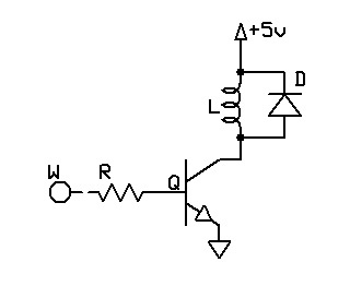
    It is common practice to put a signal diode (i.e. 1N4448) in parallel with the relay coil to suppress the back EMF generated when turning off the relay.

    If this diode is in place, then there is nothing wrong (that I can tell) with having the LED in parallel with the relay.

    Comment


    • #3
      I'm sorry... technically, "back EMF"

      isn't really the right term to describe the voltage spike that occurs when you turn off the relay. However, the voltage spike occurs nonetheless, and the back biased diode in parallel to the coil will fix the problem (as illustrated above). Note that the circuit shown above uses a transistor to turn on/off the relay instead of a mechanical switch. We only care about the diode they show connected accross the terminals of the relay.

      Good luck!

      Comment


      • #4
        Thank you for the response! You answered my question.

        Yes, it is a 12V relay. I have a protection diode wired across the relay coil, with the diode's cathode at the positive end of the relay coil.

        I wasn't sure if it was OK to connect the LED-Resistor string to the negative coil of the relay without them being grounded, for fear of introducing a positive voltage at the negative end of the coil. My lack of understanding about what is going on in the relay and the role of the protection diode made me worried.

        Thanks again for the explanation!

        Comment


        • #5
          Depending on the resistance of the coil winding you could just put the LED in series with the winding of the coil.

          A 12V relay will typically trip with as little as 7-9 volts applied. 12V is really just a nominal number, not a strict limitation. If you have to add a little resistance in series to get the current through the LED to your design spec, the relay will likely still trip.

          Alternatively, you can use an LED that requires a higher current and ditch the resistor. All LED's are not made alike. A quick browze of your relay tech sheet and a look in Mouser for an appropriate relay should get you a pair that works fine together without much trouble.

          The LED around the relay will also keep reverse voltage from damaging the LED in this scenario. LED's are typically rated for pretty low PIV's.

          I have all of the relays in my 5 channel amplifier wired this way. Not becasue it is the best but because it was the most convenient. The LED's are on the footswitch, which makes it really easy to see where I'm at as well.

          Good luck.

          -Chris

          Comment

          Working...
          X