Ad Widget

Collapse

Announcement

Collapse
No announcement yet.

master volume with pentode preamp valves

Collapse
X
 
  • Filter
  • Time
  • Show
Clear All
new posts

  • #16
    Originally posted by soundmasterg View Post
    Without a cathode follower after the EF86, you don't want to go much lower than a 1M volume pot on the output or you choke the EF86 down so much it doesn't work very well and it compromizes the tone you can get out of it too. Using a cathode follower buffers the output and allows you to maximize the gain out of the EF86 (or another pentode type) and get the tone you want out of that stage, and presents a more optimum impedance for any following stages too. It also works well with a tone stack after the CF because the output of a cathode follower is very low so there are much less gain losses than if you put a tone stack right after the EF86. You're just thinking of resistance, but the impedance is what matters here.

    Let me put it this way....if you had an EF86 going into a CF using half a 12A*7, and then a gain stage using the other half of the 12A*7, you would get more total gain than if you used an EF86 going into 2 12A*7 stages, and the tone would be better and would cause less problems trying to tweak it to work right. If you haven't yet, check out the cathode follower circuit....its one of the most useful ones out there!

    greg
    thats alot of help, i never really knew what a cathode follower was/did until this. i was under the impression that it was something in the tone stack or something. i had a bit of a read about what it was and then dound it in some circuits, and realised that i overlooked them in the past. whenever i would follow the signal through a schematic id get a bit comfused at the cathode follower thinking it was just a regular gain stage.

    must seem silly to kost people in the know, but thwnks for bringing it to my attention.
    Comment


    • #17
      Yes, I know what you mean. Tubes seem so abstract.
      It was mentioned directly-coupled into the CF. Does this mean tie the high voltage plate off the pentode straight into the grid of the CF?
      Define you terms is what I hear at college these days. By gain do we mean the collective momentum avail. to pyle drive the grid of the output tube or, as I'm so assuming, the distortion shaping that's happening in the preamp? Some of the heaviest amps these days are using very clean and wide bandwidth KT88s so the preamp is doubly cruical for overdrive-meltdown. I guess there is always oppposing 1N34a diodes but then one needs a recovery stage as the volume take a 40% drop. I tried this recently and got *nuclear* levels of incision so better tone her down again. But the mayhem!
      I think there is a lot of tone potential in this circuit as your not running through Megs upon Megs of serial reistance which is blanketing and narrowing our tone. But a guy has to have massive distortion on tap as well as "Ampeg" clean for pedals. So the MV is the guitar's then?

      Comment


      • #18
        Originally posted by Guitarist View Post
        Yes, I know what you mean. Tubes seem so abstract.
        It was mentioned directly-coupled into the CF. Does this mean tie the high voltage plate off the pentode straight into the grid of the CF?
        Define you terms is what I hear at college these days. By gain do we mean the collective momentum avail. to pyle drive the grid of the output tube or, as I'm so assuming, the distortion shaping that's happening in the preamp? Some of the heaviest amps these days are using very clean and wide bandwidth KT88s so the preamp is doubly cruical for overdrive-meltdown. I guess there is always oppposing 1N34a diodes but then one needs a recovery stage as the volume take a 40% drop. I tried this recently and got *nuclear* levels of incision so better tone her down again. But the mayhem!
        I think there is a lot of tone potential in this circuit as your not running through Megs upon Megs of serial reistance which is blanketing and narrowing our tone. But a guy has to have massive distortion on tap as well as "Ampeg" clean for pedals. So the MV is the guitar's then?
        the master volume was for the guitars input, but i could always use the other input for guitar aswell, depending on the sound i want. the distortion was going to be generated in the pamp by overdriving the ef86. ive got a bit of a draw up for the design (without the details on values for some of the things and simplification of some of the stages) ill post it up later tonight for anyone interested.

        Comment


        • #19
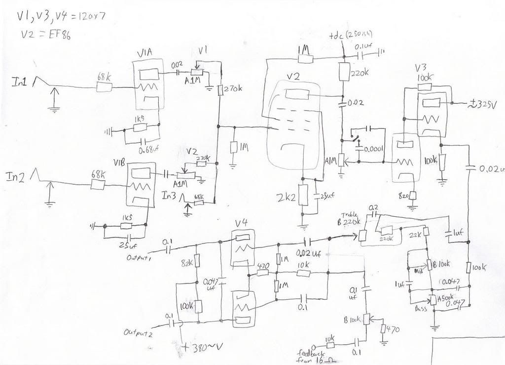
          heres the draw up i have, i didnt draw in the power supply. i gave aproximate voltages on wires that appeared from nowhere (if only you could do that in a real amp). the ef86 has values for the parts that are a bit of a combination between the phillips datasheet, an ac4 schematic and a matchless dc30 design, but i will deffinately read up about it more than i have and maybe do a bit of experimentation (especially after reading through some of the responses in the "ef86 pentode" topic).

          the design uses elements from a bassman, and has a hiwatt tonestack (in more of a bassman configuration with the tonestack after a cathode follower)

          i just noticed that i forgot to draw in one of the resistors on the LTP, so no need to mention that.


          what do you guys think. do you think using the bassman configuration would take away from the firm sound from a hiwatt? its only a bit of a initial concept, and ill go through it a fair bit before doing too much with it. i expect the design to be changed in quite a few ways before i make it. i will be getting the parts around christmas time anyway so making it will be a ways away.

          thanks for any help

          Comment


          • #20
            First thing I noticed is that with either unused channel's volume control set to zero... there will be no signal from the other or to any other stage past that point.
            You'll need to isolate those volume pots.
            You might want to bypass your screen to ground with a capacitor on the preamp pentode too.
            I think you need two more resistors in the PI for a NFB loop.
            A tail resistor and a way to lift it from ground to insert NFB.
            Bruce

            Mission Amps
            Denver, CO. 80022
            www.missionamps.com
            303-955-2412

            Comment


            • #21
              Now would a 6BM8 drop into that pentode area as well. I'm not sure if these are as good as the ef86?
              You're amp looks like it will really snarl.

              Comment


              • #22
                Originally posted by Bruce / Mission Amps View Post
                First thing I noticed is that with either unused channel's volume control set to zero... there will be no signal from the other or to any other stage past that point.
                You'll need to isolate those volume pots.
                You might want to bypass your screen to ground with a capacitor on the preamp pentode too.
                I think you need two more resistors in the PI for a NFB loop.
                A tail resistor and a way to lift it from ground to insert NFB.
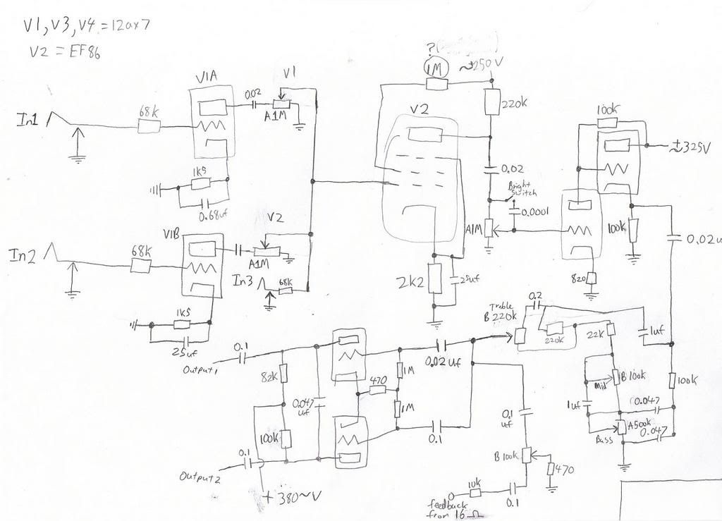
                heres the revision. regarding the NFB and PI, i realised that i thought some wires were connected on the bassman schematic when they werent, so i think ive fixed that.

                ive also isolated the channel 1&2 volume pots via 270k resistors.

                ive bypassed the screen to ground via a cap as you mentioned, as well as some other changes to the ef86 circuitry. did a bit more research and i think i understand it better, and have made some descisions on values.

                ive also added a deep cap where the bright switch is, so i can have bright-norm-deep on a sp-dt on-off-on switch. should add to the versatility of it, especially for when using it for bass. does anyone have any ideas for the value of this cap? i cant seem to find any bass amps with them in it to get an idea for the value.

                do the fixes seem about right?

                im thinking about moving the parts of the circuit around for more of a hiwatt layout, but thats just a matter of shuffling and copying.


                thanks for the comment guitarist, dont know about the sbm8, but i might have a look.

                Comment


                • #23
                  You forgot your plate resistors and B+ supply for V1A and V1B. Your feedback network is broken too (the stuff between the 16 ohm tap and the PI)
                  "Enzo, I see that you replied parasitic oscillations. Is that a hypothesis? Or is that your amazing metal band I should check out?"

                  Comment


                  • #24
                    Originally posted by Steve Conner View Post
                    You forgot your plate resistors and B+ supply for V1A and V1B. Your feedback network is broken too (the stuff between the 16 ohm tap and the PI)
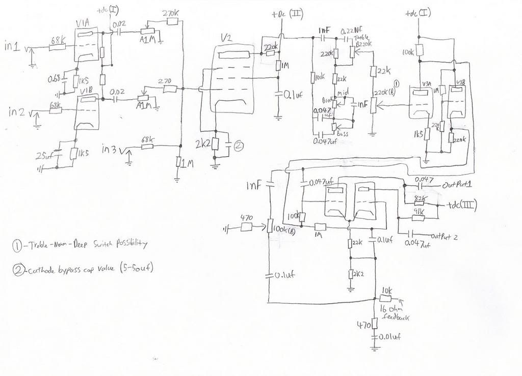
                    ive just drawn up the hiwatt style design, which is essentially copying the hiwatt dr103 after the ef86. this should probably give it more headroom which is important when using it as a bass amp, and would be useful if i was ever going to get near the breakup point when using it for guitar.

                    i remembered to draw the plate resistors and b+ on this design, but forgot to give the resistors a value, but that can be fixed.

                    i havent given the bypass cap on the ef86 a value, i was going to check out some different designs to get an idea, might just use a 25uf-25v to keep it simple.

                    i am thinking about using the bright-norm-deep boost on this amp like the bassman design, but i dont know if it will do much as the signal has already gone through the equalisation, or would it still be useful? do these type of boosts become less effective as volume is turned up (due to more signal going through the pot making a bypass not make as much of a difference)?

                    heres the schematic.


                    what type of PI is that (its copied from the hiwatt), doesnt look too familiar to me, but i dont know that much anyway.

                    is that a form of a cathode follower after the tone stack, or is it a different thing that does a similar thing.


                    thanks for the help, and sorry to keep the thread going so much, im sure some people are a bit bored by it.

                    Comment


                    • #25
                      Originally posted by Guitarist View Post
                      Now would a 6BM8 drop into that pentode area as well. I'm not sure if these are as good as the ef86?
                      You're amp looks like it will really snarl.
                      Guitarist, The pentode in a 6bm8 is an output device. A 6an8 would work in the preamp position. You could then use the triode as a cathode follower.

                      DG

                      Comment

                      Working...
                      X