Can someone tell me what this actually means? I know what voltage drop is, but get in the weeds when it comes to rectifier tubes and real world applications.
Ad Widget
Collapse
Announcement
Collapse
No announcement yet.
Rectifier tube voltage drop
Collapse
X
-
A silicon diode rectifier has about a 1 volt drop across it. So 500v becomes 499v say. A tube rectifier is nowhere near as efficient. The tube has essentially a resistance inside. So when you would expect say 500v B+ with silicon diodes, you might see only 450v with a rectifier tube. SO if you make your amp switchable between diodes and a tube rectifier, you will expect the B+ voltage to drop a considerable amount when switched to tube rectification.
The amount of current drawn through the tube makes a difference, as does type of tubes. Others I am sure have it in memory, I don;t recall what typical drops are for the popular rectifier tube types.
The effective internal resistance can be approximated in a silicon diode supply by adding a series resistor. Some call that a "sag resistor", because as the current through the resistor rises, the voltage dropped across it does too, thus lowering the voltage in the circuits. Sag. SO the tube rectifier adds sag to your amp.Education is what you're left with after you have forgotten what you have learned.
-
Here's a little chart that shows the drop and other specs for various rectifier tubes.
I'm not sure what voltage they were measuring at, but it gives you an idea of how they compare to each other.Attached FilesOriginally posted by EnzoI have a sign in my shop that says, "Never think up reasons not to check something."
Comment
-
Yes, the reason I am asking is because I am compiling such a chart to have handy at my bench. But, the concept of why voltage drop is a factor is still fuzzy to me. Is it what makes different rectifiers in the same octal class produce different DC output given the same applied VAC? And is it because it has to be expressed in relative terms with regard to the AC input? I am on the outside edge of my understanding here.It's weird, because it WAS working fine.....
Comment
-
Exactly. Mostly what I keep in mind are the 3 common octal base tube rectifiers. 5Y3 being the weakest, 5U4 intermediate, and 5AR4/GZ34 strongest. IIRC the less commonly used 5R4 falls between 5Y3 and 5U4.Originally posted by Randall View PostIs it what makes different rectifiers in the same octal class produce different DC output given the same applied VAC?This isn't the future I signed up for.
Comment
-
That´s easy once you remember (because you *already* know it ) what the problem is:
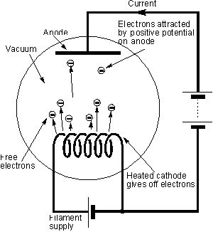
In a vacuum tube diode/rectifier you have a very hot cathode, a normal temperature plate, all inside a glass (sometimes metal) hermetically sealed envelope and with vacuum inside.
Now vacuum is the best *insulator* in the Universe !!!!!!

So in principle *forget* about any current at all passing between them.
Now Edison discovered (it was an annoying phenomenon for him) that incandescent lamps became tainted with some dark matter depositing inside glass bulbs, plus filaments weakening somehow and eventually thinning so much (at some points) that they blew open, so he (correctly) reasoned some filament material was evaporating, but didn´t research further.
Now some other experimenter wanted to solve that, so he added an electrode inside the glass bulb and applied different voltages trying to attract the mystery particles and keep them away from the glass surface.
He was very surprised when he found 2 things:
1) polarity matters.
He was not picking full "evaporated metal" atoms (temperature was not high enough for that) which would be basically neutral and work both ways but "something" which was attracted only by positive voltages ... so they had to be Electrons.
2) he got 1000000 times more electrons than he expected, so many that he could actually measure *current*
Going one way only, of course, so it worked as a rectifier.
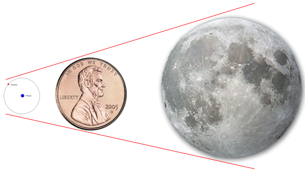
Now getting to the point: for an electron (imagine its size) , even if it already left the heated cathode and it´s floating in a cloud around it, the plate is as far as the Moon, literally.
Those 4 to 8 mm seem that, considering an Electron is just .... let´s use a comparison instead of filling the page with zeros:
"an electron is to a penny what a penny is to the Moon"

So to travel that immense amount of space (for it) you need an immense Voltage (again to it) to jump the gap.
To us Humans, that immense voltage is , say, 30/40 Volts.
So you need at least 30/40V *across* plate to cathode to pass significant current ... and of course those volts are "lost" since you can´t use them.
Suppose your transformer waveform hits 500V peak.
If the main capacitor is already at 500V ... will electrons jump? (pass current): nope.
What about 490V? ... nope.
You´ll find that for significant current to pass (whatever the amplifier needs) you´ll need, say, 50V , so the capacitor can´t charge to more than 450V, IF peak voltage available is 500V.
There, you just lost "possible" 50V, that is the rectifier drop, and of course, depends on rectifier type and current passing through it.
In fact, rectifier tube charts have a graph showing that.
That said, we use them all day long (or used to), so we already know by heart that "a certain 5xx rectifier drops yy Volts in standard use"
But if you want a more precise value, go to the datasheet.Juan Manuel Fahey
Comment
-
Expanding on what Enzo already said.
Take, for instance, a 5U4 tube data. You will a diagram such as this:

What it basically says, is that if you use this tube with as a full wave rectifier (center tapped transformer), with capacitor input filter (of value 40uF, maximum allowed for a 5U4), this is what the relation of output current and voltage looks like.
For instance, if you have a 350-0-350 transformer and your output + preamp tubes draw say 100mA (DC, in idle), the output voltage will be around 410 VDC (red lines). If you apply a signal and the current draw rises to 200mA, the output voltage will fall to around 370 VDC. Of course if you remove the tubes, output voltage would rise to a maximum possible value of 350*sqrt(2) = 493 V. Solid state diodes would give you around 492 VDC. So the voltage drop of the rectifier tube (at idle current draw) is 493-410 = 83V. Drawing more current drops the DC supply voltage, of course the screen node also drops, the gain drops and you get a compression effect ("sag"). So the tube has an internal resistance. It's not completely the same as a resistor (the curves would be straight lines in that case), but it can be approximated, and indeed the approximate resistance in ohms is given in the table to the right (our line 4's slope is apparently equivalent to 36 ohms). The higher the voltage, the slope is steeper and the sag more pronounced.
As to the physical explanation why this happens, somebody more knowledgeable will have to explain, as I have no idea
edit
OK I see Juan already did explain while I was typing
Comment
-
Here's another chart which could come in handy when you want to know how much the B+ will drop when using different rectifier tubes compared to silicon diodes. e.g. GZ34 drops 10V and 5Y3 drops 60V so changing from GZ34 to 5Y3 lowers the B+ by 50V.
Rectifier Tube Voltage Drop Chart.pdfLast edited by Dave H; 01-25-2018, 08:27 PM.
Comment
-
If your power transformer secondary VAC is a little more than the max rating of a rectifier tube you were hoping to use, then you can cut corners by wiring in 2-3 UF4007 ss diodes in series with each tube plate. That effectively adds some PIV rating, and makes the rectifier a bit more bullet proof over time as the tube starts to go gassy. Not recommended for way higher VAC.
Comment
Comment