Ad Widget

Collapse

Announcement

Collapse
No announcement yet.

understanding unintended/unwanted oscillation in guitar amps.

Collapse
X
 
  • Filter
  • Time
  • Show
Clear All
new posts

  • understanding unintended/unwanted oscillation in guitar amps.

    OK I know the basic idea of an oscillator, at about a descriptive level. I've been picking around the web to understand oscillation in vacuum tube audio amps, but haven't found a good source yet. They're either descriptive at a lower level than I understand now, or the MIT Vacuum Tube electrical engineering book from the 1950's that starts out with physics of trajectories of charged particles in high voltage fields. I got a few dozen pages in that book before stopping to review calculus and haven't gone back yet.

    If anyone knows of a book, maybe an old EE book, that would be great.

    ***
    I had created a very nice oscillator in my guitar amp, unintentionally, luckily (with all your help) figured out what was happening before I ran the amp very long, and fixed it by neatening up the wiring. Experimenting with the amp, I was able to get it to oscillate again, although not as bad as with the problem wiring. I had all the amp controls on 10, except the treble. A guitar was plugged in, and controls all on max. Got a nice hum since the guitar was pointing towards the open chassis. As I turned up the treble past some point, while watching the output tubes, suddenly the output tubes started glowing red inside (didn't cook the plates, since I turned the controls back down right away).

    On these old circuits, were these amps really that close to oscillation? Id like to understand what path(s) the feedback is occurring, and how to fix it properly, so that no matter what the setting of any controls, the amp won't go into sub or super audio band oscillation and cook the tubes (and whatever else tends to get cooked).
    The only good solid state amp is a dead solid state amp. Unless it sounds really good, then its OK.

  • #2
    Put a circuit with gain, and let the output get back into the input. Feedback. That is an oscillator.

    Stick your microphone in front of a PA speaker, it makes an oscillator - the feedback. Your guitar pickups can feed back if they get too close to a speaker.

    All that mumbo jumbo in the engineering texts is about designing a good stable useful oscillator circuit. A purposeful oscillator. A guitar amp can become an oscillator, but not on purpose. Well except for the tremolo circuit. I have never had to invoke a formula to fight oscillation in a guitar amp.

    There is an excellent, excellent book about troubleshooting analog circuits, in fact that is its title. Written by Bob Pease. It is not an entry level book, but it has tons of great stuff both basic and complex. Most texts do not get into troubleshooting. They talk of how to make a working circuit, but leave you hanging about how to fix ones that don't. I have read my copy many times, and each time I learn more stuff from it.

    When an amplifier oscillates, we have to find where the loop is - where is the path to get output back to the input. Might be the whole amp - speaker signal getting into the input jack wires - might just be one stage. (The trem oscillator is one stage in Fenders) Might be a couple stages - speaker signal gets back into phase inverter grid wires.

    Wires coupling together like that is cured by lead dress. But there are other ways that are not direct coupling of signal leads. If you ever watched your B+ as you play, you will note the voltage goes up and down with the music. Play something loud and the voltage drops, as your note tails off, the voltage comes back up. The power stage affects it the most, but other stages can as well. A common source of feedback is loss of decoupling - weak "filter caps".

    Look at a typical Fender gain stage, a 100k plate resistor from a B+ filter cap. That cap fed from a higher B+ voltage cap through a resistor, say 10k. Well, what if that filter cap opens, or loses a connection. Instead of a stable B+ at the top of the 100k, we now have 110k as a plate resistance. (100k plus the 10k resistor) Now whatever signal voltage is swaying the 100k, there is a 1/10 as large signal through the 10k. That means we have signal at the filter cap node - but no cap. If any other gain stages also use that node for power, then their B+ is also hopping around at that 1/10 signal level. And that injects the signal from the first stage into the other stage. That CAN cause feedback - oscillation.

    Instability can have various causes.
    Education is what you're left with after you have forgotten what you have learned.

    Comment


    • #3
      Not really that a big deal, the generic textbook example applies: a gain stage will oscillate IF output is fed back to input, IF in phase and IF gain higher than one.
      At what frequency?
      Well, some kind of network must favor one frequency over others .

      One example of circuits *designed* to oscillate, just to check above conditions apply, they are not pulled out of the blue:

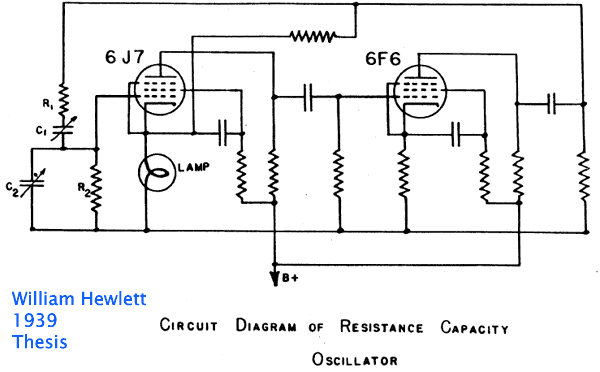
      Wien bridge oscillator.


      Hey, this guy Hewlett shows talent designing oscillators !!! I guess he should pursue a career designing them!!!! and maybe some other Lab related stuff!!!!

      We have two tube gain stages.

      They are connected in cascade (so far we are describing part of a Guitar preamp ) and signal from the second one is fed back to the first one (here on purpose, in a preamp usually by component to component or wire to wire "invisible/parasitic" capacitance, or chassis/ground small resistance, what does not make it any less real) .

      We have a frequency determining network, the "Wien network" (two resistors two capacitors) , it also modifies phase.

      In a Guitar preamp it would be stray capacitance and inductance in wiring or between too close parts, or ground resistance which is NOT zero.

      The frequency network usually has attenuation, specially if NOT expected to couple stages, but as long as you add enough gain to the soup, it will oscillate.

      The Wien bridge has attenuation 3X so 3X gain is enough, wire to wire capacitance will have tons more attenuation , capacitances involved are real small, think a pF or less , but, hey, a single 12AX7 triode gives you some 60X gain, we know those are not troublesome, but two cascaded stages give you 3600X and 3 stages 216000X ,
      And we all know that JCM800 class and higher gain preamps are a bitch to tame.

      Some amps cut highs to reduce that (small parasitic capacitance means it´s far easier to oscillate at high frequencies) but then sound tuns out to mud (are you listening MBDR? ..... or Peavey 5150?)

      So now you see once high gain (high being >50X or so) is introdiced in a circuit, it can and will oscillate, as soon as you are even a little sloppy (long parallel wires belonging to different stages) or poorly chosen ground or poorly decoupled stages (power supply is common to ALL)
      Juan Manuel Fahey

      Comment


      • #4
        Click image for larger version

Name:	IMG_7033.JPG
Views:	1
Size:	1.08 MB
ID:	848542

        HP 200CD ... I bought it 35 years ago for $15. Only thing that doesn't work is the leather handle. One of the things that will be leaving soon.

        Comment


        • #5
          You need a scope if you don't have one, or a spectrum analyzer.

          Comment


          • #6
            Thanks everyone, as usual!! And thanks for the tip on the Pease book, looking for a used copy.

            I think before I start with the books I need to draw out the layout, as closely to what I actually built as possible, then look for issues you described above. Yes, looking for a cheap used scope as well. This is cool stuff (up to and maybe just before I toast my output tube set )
            The only good solid state amp is a dead solid state amp. Unless it sounds really good, then its OK.

            Comment


            • #7
              So assuming the parts are all good, no bad caps (even though they are new, this might not be true)

              1 - long parallel wires belonging to different stages or
              2 - poorly chosen ground or
              3 - poorly decoupled stages (power supply is common to ALL)


              I can find item 1. Item 2, not enough experience to know what a poorly chosen ground is. Does this mean ground loops?
              3, not sure. I think this means that the main power supply, the dirty side, grounded together, and the low signal preamp wiring, grounded together and separately from the HV power grounds? I mean (I think): don't run a ground wire from V1 all the way to to where the power supply main HV center tap is grounded?

              But also maybe more subtle things. There is a 410v or so supply line leading to the reverb transformer. I grounded that on a lug soldered to the back of the chassis, near where the RCA jacks are located. Maybe THIS ground should be routed to near where the filter cap for this stage is grounded?

              Aside from those, lots of item 1's to look for. Esp seems to be to/from the pots. I had maybe an Ahaa moment, maybe not: The vol, treble, bass, reverb are in the 'stock' position. But instead of tremolo, I have two mid pots (turned out they are about useless, since turning them down makes the amp sound worse), but wiring to the mid pots from the two preamps runs a long way, maybe too far, under and near the reverb wiring. I thought I did a good job twisting, and also forcing the wires to run at an angle, even if not 90 degrees, but this is a possibility?
              The only good solid state amp is a dead solid state amp. Unless it sounds really good, then its OK.

              Comment


              • #8
                The issue of where and how to connect ground just seems to keep coming up.

                The skinny on ground wires is that they are not wires - they are low value resistors. So if there is any current running through them, they will generate a voltage proportional to the current. So if you have an input ground and connect it to a ground wire that is carrying current for some other task, the voltage generated by that "other task" is sent in as an input signal.

                Let's take an easy one - speaker return. Speakers have a lot of current flowing. If the speaker output jack is simply tied to the chassis, and the OT secondary is tied to the chassis somewhere else, all of the speaker current flows through the chassis. The chassis then develops a voltage between the output jack and the OT secondary. If you happen to tie a signal ground to the chassis somewhere between the OT secondary ground and the output jack, the millivolts of drop across the chassis are added to the input signal, and it WILL oscillate if the amplifier gain is high enough. Simply picking different places on the chassis to "ground" the inputs will start or stop oscillation. Same thing with heater currents. If you use the chassis for heater current, it will make for voltage drops that will cause intransigent hum.

                Another place you can get into "where do I ground" issues is with the output tube cathode grounds. It's tempting to tie these to the chassis instead of running a special purpose wire back to the power supply negative. If you do that, you've created a situation that is only different from speaker grounding as above by the currents being lower.

                This line of thinking leads to the idea of star grounding. Star grounding isn't the only way to get quiet, non-oscillating grounding set up. But it is the only way that can be proven to do so before the fact of analyzing every ground conductor for what currents flow where.

                The other ways of getting oscillation come down to coupled inductive loops and capacitive feedback. Coupled inductive loops are generally not a problem in guitar amps because the currents and loop overlaps are too small. You can get capacitive feedback from wire dress, though.

                Every conductor in the universe is capacitively coupled to every other conductor in the universe. the only thing that makes that even partially cope-able is that the size of the capacitance falls off with the square of the distance between them. But every wire in your amp sees some capacitance to other wires. And to the chassis. So wires carrying output voltages are capacitively coupled to your input wires. The only question is how big the capacitor is. The closer the wires are and the longer the length of wires being close - that is, how much of their lengths are parallel - determines how big the capacitance is. The size of the capacitance is important because that capacitance and the impedance on the input wire it feeds determines the low frequency cutoff of that path of feedback. Little capacitance - that is, wires far apart and not parallel - puts the cutoff far into the RF region where your amp's gain has fallen to zip, so no oscillation can happen. Larger capacitance, wires close and parallel, gives a capacitance in the region of tens of picofarads, and the impedance of a tube grid is high enough to let this cause oscillation.
                Amazing!! Who would ever have guessed that someone who villified the evil rich people would begin happily accepting their millions in speaking fees!

                Oh, wait! That sounds familiar, somehow.

                Comment


                • #9
                  Thanks RG and, again, everyone on the thread. Printed a copy of this thread, going to tape it together and hang it in my cube at work. Next amp, I'm going to color code by what the wire is for, e.g. brown for cathode, red for plate, blue for grid, etc. Sounds like #1 is capacitive coupling of wires running too close together, and #2 (not so far behind) is the grounding scheme.

                  Im getting there, but not so clear on currents running through the chassis. I understand it happens, but would two ground 'stars' fix that problem? I have two main ground points, but a couple of others (4) due to location.
                  1)
                  - The first two fillter cap negative leads,
                  - the positive lead from the bias filter cap
                  - center tap from the power transformer
                  are grounded together, very close to the PT.

                  2)
                  The two 100 ohm resistors that form the artificial center tap for the heater wiring are hanging off the pilot light, and grounded at a lug soldered and bolted to the chassis at the power transformer, behind the main ground star above.

                  3) All of the cathode filter/resistor grounds, all of the pot and preamp grounds are tied to another 'star' all the way on the other side of the chassis, under the corner near the first set of input jacks. Unfortunately, the grounds cathode resistor/cap for the reverb driver tube is right in the middle of the preamp ground bar. Maybe it shouldn't be, since it is fed from a big filter cap and dropping resistor right off the choke. I can move that, but its a pain to remove since there are so many leads in that eyelet, and also going to be hard to find a place to mount those 2 components.

                  4) the speaker ground wire inside the chassis (i.e the grounded side of the output transformer) is soldered to the ground lead on the output jack on the back of the chassis.

                  5) the reverb secondary ground wire is soldered to a ground lug on one of the RCA jacks, not far from the speaker jack. Its not an isolated jack, so stuff's going to move through the chassis from there.

                  6) both 1 ohm cathode resistors (bias measurement aids) are soldered right to the chassis, next to the output tubes. Easy to un-solder from the chassis and run a wire to ??? someplace. Since the power tubes are fed from the power supply node right after the choke, I think they should be grounded to the same lug that this cap is soldered to.

                  That leaves the hard stuff. I understand the wiring coupling, just don't know exactly what to look for besides parallel wiring, from different stages, then see what those wires do.

                  OK so now I understand better also why the wiring leading to/from the vol/bass/treble pots are all twisted: so some other signal wire can't induce something in that bundle?
                  The only good solid state amp is a dead solid state amp. Unless it sounds really good, then its OK.

                  Comment


                  • #10
                    I'm paying attention here too, as I have a hum I can't heat (yet) and some parasitics cancelling stuff (for now). Thanks to Mike for the step-by-step and everybody else for the remedies. I hafta confess, my amp IS a lot simpler, but as with anything True PTP, it's always the hardest part, fixing the blasted things...

                    Justin
                    "Wow it's red! That doesn't look like the standard Marshall red. It's more like hooker lipstick/clown nose/poodle pecker red." - Chuck H. -
                    "Of course that means playing **LOUD** , best but useless solution to modern sissy snowflake players." - J.M. Fahey -
                    "All I ever managed to do with that amp was... kill small rodents within a 50 yard radius of my practice building." - Tone Meister -

                    Comment


                    • #11
                      Oh, sure, after we spouted off theoretical stuff, ask for what to really DO.

                      1)
                      - The first two fillter cap negative leads,
                      - the positive lead from the bias filter cap
                      - center tap from the power transformer
                      are grounded together, very close to the PT.
                      What you're after here is the One True Ground. You must construct it. This will be on big, burly lump of solderable connections that are as conductive to each other as you can possibly make or afford. You want the One True Ground to be where all other things are referenced. It is generally good to make this be the negative lead (in tube amps, at least) of the first filter cap, and as close to the actual can of that filter cap as you can get it without going nutso. The idea here is that the first filter cap is the first line of defense from power supply ripple. You want the One True Ground right on its negative lead. What attaches there is the CT of the power transformer (or negative side of the bridge if you use a FWB) so the diode charging pulses have the shortest possible wire/lead to traverse before getting into the capacitor plates. How long the CT lead is is of no particular importance; the OTG doesn't have to be near the PT. It doesn't much matter if it is or isn't, other than for secondary reasons like how to run big wires to other stuff.

                      Also attached to the One True Ground by wires are: the positive lead of the bias cap, further decoupling cap leads, and circuit section power returns. I personally would run one wire from the One True Ground to a chassis lug, that being the chassis ground, and isolate all other signal ground connections from chassis, including input jacks and output jacks.

                      2)
                      The two 100 ohm resistors that form the artificial center tap for the heater wiring are hanging off the pilot light, and grounded at a lug soldered and bolted to the chassis at the power transformer, behind the main ground star above.
                      Likewise, I would take one wire from the artificial center tap to the One True Ground. If that is the only wire to the heater CT, there can be no current through it, and hence no voltage across it. There will be some through0-the-vacuum leakage of electrons from cathodes, but this is going to be small.

                      3) All of the cathode filter/resistor grounds, all of the pot and preamp grounds are tied to another 'star' all the way on the other side of the chassis, under the corner near the first set of input jacks. Unfortunately, the grounds cathode resistor/cap for the reverb driver tube is right in the middle of the preamp ground bar. Maybe it shouldn't be, since it is fed from a big filter cap and dropping resistor right off the choke. I can move that, but its a pain to remove since there are so many leads in that eyelet, and also going to be hard to find a place to mount those 2 components.
                      I would clear up other issues and return to this "clot" later if it's already built. The general idea is to clump, for instance, the ground returns for one or two tubes which all do the same work on the same signal at a time. Then run a ground wire back to the One True Ground for that lump. One input preamp/recovery channel is a good lump. The return currents for the clump will be moderate, and will still cause some feedback from the resistance of the wire back to the One True Ground, but since the return current will all be either in phase or correctly out of phase, it minimizes any chance for cross-channel feed, hum pickup, or oscillation.

                      Another lumping strategy is "whatever is decoupled by one decoupling cap", although that is sometimes not well thought out in some amps I've seen.

                      Wherever the word "driver" gets involved, consider making that its own lump, the reverb driver tube being a good example. Likewise, the tremolo circuit generates wobbles and ticks. If you can afford it its own ground wire for the lump, so much the better.

                      PI makes a good lump, as does the hugely-advisable power output tubes cathode return.

                      4) the speaker ground wire inside the chassis (i.e the grounded side of the output transformer) is soldered to the ground lead on the output jack on the back of the chassis.
                      Lots of amps get away with this. I personally would isolate the output jack, run the OT secondary to the jack, and then run a ground reference wire back to the PI circuit if the amp uses secondary feedback. This forces the big currents to flow only to/from the OT and speaker, and gives you a clean, low current reference back to the PI cathode circuit for feedback, presence, etc.

                      5) the reverb secondary ground wire is soldered to a ground lug on one of the RCA jacks, not far from the speaker jack. Its not an isolated jack, so stuff's going to move through the chassis from there.
                      I just got from Mouser an order with RCA chassis-mount phono jacks and fiber insulating washers for converting a phono jack on an amp I'm working on. Different setup, but similar motivation. RCA phono jacks can be had in 0.25" hole varieties, and the fiber insulating shoulder washer for that ID can be had in 0.375" hole diameter. The RCAs cost about $0.50 at mouser, and the shoulder and flat washer pair was another $0.25. Just sayin'

                      On the other hand, if you are good at removing other junk from the chassis, having one return on the chassis may just squeak by. Nothing is perfect. All we're doing here is getting the noise down to good enough.

                      6) both 1 ohm cathode resistors (bias measurement aids) are soldered right to the chassis, next to the output tubes. Easy to un-solder from the chassis and run a wire to ??? someplace. Since the power tubes are fed from the power supply node right after the choke, I think they should be grounded to the same lug that this cap is soldered to.
                      If you possibly can, join them and give them their own wire to the One True Ground. The output tubes' current has to return to the negative of the first filter cap. By only giving it one wire to do it on, you force that current not to pollute other ground voltages. This one is a biggie, as the combined current from the tubes is a full wave rectified replica of the currents going through the OT primary.

                      Notice that ALL useful DC current in the amp ultimately passes through the negative lead of the first filter cap. Knowing that, we can control exactly how it gets there.

                      That leaves the hard stuff. I understand the wiring coupling, just don't know exactly what to look for besides parallel wiring, from different stages, then see what those wires do.
                      Frankly, this issue is often overblown. With other grounding issues fixed, you can often probe with chopsticks and see what wire causes what critical result. True, it can happen, but don't sweat it much other than to be really careful where the wire from a grid runs, and keep it separated as much as >practical< from unrelated anode wires.

                      OK so now I understand better also why the wiring leading to/from the vol/bass/treble pots are all twisted: so some other signal wire can't induce something in that bundle?
                      Yes. Although an obsessive would look at what control currents and such flow in the wires in the bundles and dink with those. I'd leave that for a second pass until you've cleaned up the bigger targets.

                      In addition to this, I recommend:
                      > Use Amphenol or Switchcraft jacks with a nylon body and 3/8" bushing diameter for all input jacks; the output jack might well be done this way as well. This is an easy way to get the jacks off the chassis and close off one more hole for noise. If you get RF, run a 100pF ceramic cap from the input jack ground lead to a ring terminal on the bushing to divert RF coming in off the antenna/cord into the chassis.
                      > See if you have remaining problems. You may want to rewire the decoupling caps in the DC distribution chain with their own ground wire to the One True Ground. You might not need to, but it's there if you need it.
                      > Three wire your amp. Use an IEC AC inlet. Run the safety ground to the chassis on its own, dedicated connection lug. Don't run it to the One True Ground, or where signal ground goes to the chassis. It's doing a different job.
                      Amazing!! Who would ever have guessed that someone who villified the evil rich people would begin happily accepting their millions in speaking fees!

                      Oh, wait! That sounds familiar, somehow.

                      Comment


                      • #12
                        Originally posted by R.G. View Post
                        Frankly, this issue is often overblown. With other grounding issues fixed, you can often probe with chopsticks and see what wire causes what critical result. True, it can happen, but don't sweat it much other than to be really careful where the wire from a grid runs, and keep it separated as much as >practical< from unrelated anode wires.
                        Great summary R.G. - grid wires are important, but just want to add that it also helps to pay attention to the biggest noise sources in the chassis. By shielding or carefully routing the noisiest lines away from any circuitry, you reduce their coupling to all grid lines and circuitry. In typical amps, the highest level signal lines are the power tube plate wires, reverb driver plate circuit, and the PI output lines. (Also PI input for cathodyne PIs)
                        “If you have integrity, nothing else matters. If you don't have integrity, nothing else matters.”
                        -Alan K. Simpson, U.S. Senator, Wyoming, 1979-97

                        Hofstadter's Law: It always takes longer than you expect, even when you take into account Hofstadter's Law.

                        https://sites.google.com/site/stringsandfrets/

                        Comment


                        • #13
                          Thanks! Lots of stuff to do. What to do, what to do...

                          So, way back, when I knew zero (now I know 0.0000001%) I had thought that I could get away with using a Deluxe AB763 eyelet board, shoehorned into a chassis for a Deluxe AB763 Fender Reverb, leave the tremolo parts off the board, and shoehorn in reverb parts. The reverb transformer is not sitting above the reverb send/recieve tubes, and the reverb wiring is not coming down through the chassis between the two either, its coming in way too close to V2 preamp tube. After reading and re-reading this thread, and looking at the actual layout on my amp, it doesn't make sense what I did: reverb components are clumped together incorrectly, and wiring is all too close to the sensitive preamp tube and wiring.

                          So I just ordered a Deluxe Reverb AB763 double turret board, and will pull the components off the wrong board, and put them on this one, since it will be a heck of a lot easier to implement all of the necessary OneTrueGround concept. And with a double turret, I can put the board close to the chassis, and not have to worry about stuff going under the board, and the wiring leading from the board to the tube pins will be a lot shorter, since they won't have to drop 3/4" down to the chassis.


                          OK So I got the general concept, thinking about ways to 'clump and run'. So, I don't want the second big star on the chassis for all the preamp stuff. I want a couple of clumps, then run a ground wire back to "the" ground clump. I think I can accomplish this by cutting the little brass bar I used for a grounding bar in a couple of pieces (2 or 3) wiring stuff to that appropriately on the pot side of teh board, then running a wire from each piece of the bar back to the BigGround.


                          I have a mechanical problem I haven't figured out, though. So, will have 2 x 100 ohm resistors from the artificial center tap, tied together on one end and a wire from that to ground; then the two 1 ohm bias measurement resistors tied to a wire, then that run to ground. This happens in 4 or 5 places These resistors are not soldered to a solid connection on both ends, and I think mechanically that's not a good idea. I had tried putting a terminal strip next to the preamp tubes for the 2 68k grid stops, one end soldered to the tobe socket pin and the other end to the terminal strip, but it was WAT too crowded in there and made the wiring runs messy going from the tube pins to the eylelet board, since they had to run around the terminal strip.

                          Im looking for something to replace the big terminal strips that serve a similar function: just hold down one end of a resistor or two resistors, (the resistors have a wire soldered that will go to ground). Something I can screw to the chassis that is insulated but can hold the loose end of the resistor. If everything gets vibrating in there, and it will with the 12" speaker so close to the chassis, Im afraid these 'one loose end' resistors will have a problem with one of the connections after a while. And, of course, Id like to pass this amp to my great grandchildren

                          The amp is already built, but Id like to fix everything possible, to get rid of what is left of the hum, and also kill the oscillation. I don't have isolating jacks, but it sounds like the critical jacks to isolate are the reverb and speaker jacks, since a lot of juice flows through those. Will do everything else, but the input jacks are not isolated . . . and see what happens. I think Id have to remove everything from the chassis to re-drill to be able to fit isolated jacks on the front panel. The back panel has a lot less 'stuff' on it, and I can cover the pots whlle drilling the back panel to keep shards out.

                          Thinking about a way to hang several pieces of small round brass bar from the pot side of the new eyelet board. Or maybe I don't have to actually physically mount it since each piece will have several ground wires holding it in place. Its going to get some vibration, but maybe it will be OK mechanically. I had tried one of those plastic nylon wire tie downs, but it didn't fit the bar exactly, so it would slop around anyway, so I left them off.

                          Im going to ask one of my former co-workers to make me a laser cut nameplate. this amp is going to be MEF-DLX-V01.
                          Last edited by mikepukmel; 02-09-2018, 12:44 PM.
                          The only good solid state amp is a dead solid state amp. Unless it sounds really good, then its OK.

                          Comment


                          • #14
                            One advantage of a spectrum analyser (such as a soundcard and software style) is that it can confirm the noise floor of an amp looks nice and low and sort of constant across the spectrum when all the pots are turned down and there is no input signal (eg. shorted input socket), and can then help fault find such issues as unexpected feedback when pot levels are raised and when input signal is applied.

                            In an ok amp, the noise floor should moderately rise with pot level increases, and broad smooth frequency sections can show up related to tone filtering. If the amp has parasitic coupling issues, they can sometimes be seen as rapidly growing spectral peaks coming out of the noise floor - usually in the higher frequency range - when pots are varied and/or signal applied. A simple soundcard will give you at least 20kHz bandwidth, which is likely to cover many forms of inadvertent feedback from parts or wiring that are too close together, or not adequately screened.

                            Comment


                            • #15
                              Take 3: Might have had the last oscillation problem (pots at certain settings), due to adding reverb components and wiring in places they were not located in the original design. The HV reverb wiring was way close to the V2 preamp tube wiring <big frown>. The original amp, the HV wiring ran between the two reverb tubes (Live, ask lots of questions of great people, and learn)

                              So, screwed up and ordered a second non reverb board. Had a arrghh moment, orderd a 3rd board that is a reverb board. Dry fit is MUCH better than the other board. This one is much closer to the original dimensions. So, the turrets for V1 wiring are really close to V1, the turrets for reverb are very close to the reverb tubes and so on.

                              Working on making the grounding scheme a couple of levels better, due to all of your awesome explanation and suggestions. The grounds for all tubes fed by a cap are run to the same ground. The only problem in getting this 100% is that the ground side of the cathode cap and resistor for the reverb is smack in the middle of the other tubes. <frown> So, it will be a lot better, but not poifect. (Queens NY for perfect).

                              Click image for larger version

Name:	DSC_3120_v1.jpg
Views:	1
Size:	351.5 KB
ID:	848912


                              Thinking about re-using the brass bar like this, running preamp and input grounds there then run a ground wire someplace that makes sense. Not perfect, but ... better

                              Click image for larger version

Name:	DSC_3121_v1.jpg
Views:	1
Size:	187.2 KB
ID:	848913

                              So, HV wires separate from sensitive preamp inputs/outputs, grounding tubes that are fed by a cap, with that cap. Reduce the number of ground points on the chassis by 2. Still not a true "star" but closer.

                              Another benefit of this nice turret board is that it will be mounted a lot closer to the chassis, so the wiring to/from the tube side will be a LOT shorter and neater.

                              Now I only have to fight with that shielded wiring again with my 11 right thumbs and 17 left thumbs.
                              Last edited by mikepukmel; 03-10-2018, 06:15 PM.
                              The only good solid state amp is a dead solid state amp. Unless it sounds really good, then its OK.

                              Comment

                              Working...
                              X