Ad Widget

Collapse

Announcement

Collapse
No announcement yet.

Amp power supply questions.

Collapse
X
 
  • Filter
  • Time
  • Show
Clear All
new posts

  • Amp power supply questions.

    Hi Guys, long time since I've posted but I hope you may be able to advise me.
    I'm building an amp using a kit I bought that uses the LM3876T chip. The design was in Silicon Chip March 1994 issue.
    No real problems with that.
    The pre amp is a kit I bought that uses 2 x Raytheon JAN6418 sub-minature pentodes.

    The idea for the amp is a light weight guitar amp to use for playing jazz.
    I'm looking for a clean sound and with the tubes for the pre amp, a bit of warmth. And because of my age, lightweight.
    I plan to use a 10" Jensen MOD speaker rated at 50 watts, the same as the power amp
    and mount this all in a 12" cube made from 12mm thick marine ply. Open backed.

    Now the power supply, I'm using a toroidal trans and after rectification it will supply +/- 35Vdc rails.
    The pre amp is made to use a 9v battery as it only draws 11mA.

    Now if I place a voltage divider on the + 35v rail, to draw off 9v for the pre amp,will that affect the pwr chip too much?
    What sort of voltage drop should I expect on the 35v rail.
    If it does have too much of an effect, is there a way of balancing up the -35v rail to even the voltages out?
    I'd rather have one pwr supply but do have a small pwr trans I could use for the pre amp if I have to.
    Hoping you can help. Cheers Col.
    Last edited by OldSolder; 03-10-2018, 11:50 PM.

  • #2
    Originally posted by OldSolder View Post
    Now the power supply, I'm using a toroidal trans and after rectification it will supply +/- 35Vdc rails.
    The pre amp is made to use a 9v battery as it only draws 11mA.

    Now if I place a voltage divider on the + 35v rail, to draw off 9v for the pre amp,will that affect the pwr chip too much?
    What sort of voltage drop should I expect on the 35v rail.
    The pre-amp should have negligible effect on the +35V rail. I'd use a series regulator rather than a voltage divider. It will provide a more stable voltage and use less current.

    Comment


    • #3
      I can't see how the preamp could only draw 11mA, as the 6418 heaters look to require 100mA @1.25V http://www.mif.pg.gda.pl/homepages/f...127/6/6418.pdf
      And it's described as a mini power pentode, so doesn't seem entirely suited for the application.
      Have you got any info on the preamp, eg schematic?

      A cube cab may not be ideal, as the depth may tend to make it a tuned port; I suggest to bring the depth down to be similar to regular small guitar open back cabs, eg 10" max. But it may not be a problem, and even it it turns out to be too resonant at 12" deep, it could always be cut back later.
      My band:- http://www.youtube.com/user/RedwingBand

      Comment


      • #4
        Congratulations on your new project

        Please post the schematics you are mention, or at least direct clickable links, so we know what are you talking about.

        Please fill Country data in your Member page, "Silicon Chip" and those pesky microtube preamps hint at Australia but I might be wrong

        Now to questions:

        2) no need to balance anything, compared to the about 2A that chipamp may "eat", 11mA is *nothing*
        In any case we need the Schematic(s) ?

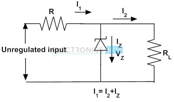
        1) that´s what Zener diodes were invented for: getting stable voltage even if current through it varies, an "intelligent voltage divider" which will always give you 9V.


        "Unregulated voltage" is +35V

        "Rl" is your preamp, which you say needs 11mA (I2)

        The Zener diode needs "some" current through it to "Zene" (Iz), for example another 11 mA, so you will pull from main supply (35V) some 22mA total (I1).

        So R has 35V at one end, 9V at the other, it drops 35-9=26V and current is 22mA , so Ohm´s Law tells us its value is:

        >>>>>>> brainfart starts .... I *said* 22mA but *used* 11mA
        Corrected Math follows:
        26V/0.022A=1181 ohms, call it 1200 ohms (a standard value and close enough).

        1200 ohms is a standard value end close enough in this case (current is not critical) .

        It will dissipate: (26*26)/1200=0.56W so choose a 1W resistor.
        <<<<<<<<<<<<<<<<<<<<<<<<<<<<<<<<<<<<<<<<<<
        Last edited by J M Fahey; 03-11-2018, 12:18 AM.
        Juan Manuel Fahey

        Comment


        • #5
          Yes, a schematic would be good. I see now I have read the data sheet Pete posted that the 6418 heaters are 1.25V @ 10mA so there has to be some way of providing 1.25V

          Edit: I call "an intelligent voltage divider" a shunt regulator

          Comment


          • #6
            Originally posted by pdf64 View Post
            I can't see how the preamp could only draw 11mA, as the 6418 heaters look to require 100mA @1.25V http://www.mif.pg.gda.pl/homepages/f...127/6/6418.pdf
            And it's described as a mini power pentode, so doesn't seem entirely suited for the application.
            Have you got any info on the preamp, eg schematic?
            I had thought the same, but datsheet actually says 10 mA

            As of it being a "Power" pentode, yes, it´s so described .... but "power" output is 2.2mW best case, and one suggested load impedance is 100k, so it´s firmly inside the typical Preamp area.

            One reported problem is microphony, plus Seymour Duncan (who used them) got mad because solder didn´t take very well on old tube leads (easily 50 years old) causing random scratching noises (think dirty potentiometer) , I suggest light burnishing them with steel wool before soldering.

            I suggest OldSolder to build and try this project on a piece of wood before punching and drilling a chassis , just in case.
            I fear microphony and *maybe* ´poor solder connections and in any case it would not supply much of the desired "warmth".

            Might work perfect, of course, in that case you go on.

            If not, I would give serious consideration to Rodd Elliot´s Guitar Preamp project, pulling the clipping diodes and master volume since they will not be needed here.
            Or add a switch to take them out/in circuit at will.

            VERY good "Fendery" sounding preamp, will be fine for Jazz.
            And you can buy the ready to solder PCB locally

            The MOD speaker is very good.
            Juan Manuel Fahey

            Comment


            • #7
              Thanks for the replies gents I really appreciate it.
              Pwramp.pdf

              The heaters are supplied by the L4949 chip at 5v.
              Is the Zener diode voltage divider really that much better than a series reg?

              As far as the microphonic thing with the tubes, the kit supplies grommets, 2 to each tube.
              I thought of hot melt gluing them to the PC board.
              Going by the blurb the pentodes have a gain of 10 and there is a trim pot between them
              which could wind the overall gain to 100.
              I'm hoping I might be able to drive the second tube just enough that the sound warms up a little.
              It has switchable high and lowpass filters so once set there would only need to be a simple tone control to roll off the tops.
              I'm also looking for simplicity.Vol and tone controls only.
              Once again thanks for your help. Col.

              Comment


              • #8
                Lay the tube leads on a board and take some emery cloth to them to shine up the wire leads before soldering.
                Education is what you're left with after you have forgotten what you have learned.

                Comment


                • #9
                  Originally posted by Enzo View Post
                  Lay the tube leads on a board and take some emery cloth to them to shine up the wire leads before soldering.
                  There was no need to. They soldered up easily and at a relatively low temp.

                  Comment


                  • #10
                    If I wanted 9v from a 35v supply I'd use a 7809 regulator bolted to the chassis.

                    Comment


                    • #11
                      With only 11ma draw, he ought to get away with a 78L09 in a TO92.
                      Education is what you're left with after you have forgotten what you have learned.

                      Comment


                      • #12
                        Ah, yes. One caution, though - some spec sheets list the maximum input as 30v, others 35v.

                        Comment


                        • #13
                          Is it higher for the TO220s?
                          Education is what you're left with after you have forgotten what you have learned.

                          Comment


                          • #14
                            I only found 35v listed for the TO220s (40v input for regulator types over 20v). It's easy enough to find 35v 78L09s, though.

                            Comment


                            • #15
                              It's only 11mA you could put a 1k resistor in series to reduce the input voltage by 11V

                              Comment

                              Working...
                              X