Ad Widget

Collapse

Announcement

Collapse
No announcement yet.

R3000 Diodes, output tube plate to ground.

Collapse
X
 
  • Filter
  • Time
  • Show
Clear All
new posts

  • #31
    The smaller 7mm and 10mm disk size MOV's have pretty low capacitance (below 100pF), and relative to the typical shunt capacitance across a half-winding are imho benign. If it was a hi-fi amp, then that capacitance could be used as a zobel network option out well beyond 100kHz.

    I'd suggest making the MOV 1mADC rated voltage noticeably more than B+, then a MOV across each half-winding would only start to load up each plate's waveform on voltage excursions at or beyond what the diodes would do to one half-winding at that time. MOV loading would get progressively heavier if the energy in the winding is sufficient to push the voltage higher - even 7mm disks appear to have a sufficient continuous power dissipation capability when I looked at the levels a few years ago. Loudthud presented some illuminating X-Y plots of plate voltage-current in a PP guitar amp showing the 'level' of voltage excursion beyond the +/- B+ span. Some detailed notes are in https://www.dalmura.com.au/static/Ou...protection.pdf.

    MOV's aimed for 240Vac and 415Vac applications are quite common.
    Comment


    • #32
      It's important to recognize that the pics in trobbins paper were taken with the speaker connected. Speaker inductance (IMHO) is the dominate source of spikes that the R3000 diodes are meant to deal with. The speaker X-Y clips I posted in this thread:

      http://music-electronics-forum.com/s...ad.php?t=35493

      were actually created with a solid state amp so none of the spikes were coming from an output transformer. Spikes are clamped by an MOV to ground and diodes in series with the Drains prevent the Drain-Source diodes from clamping the spikes. MOSFETs are connected in a common Source configuration with Sources going to the +/- rails. Also see the pic in post 52 of this thread:

      http://music-electronics-forum.com/s...t=39829&page=2

      Plate Voltage spikes of a tube amp going 600V negative.
      WARNING! Musical Instrument amplifiers contain lethal voltages and can retain them even when unplugged. Refer service to qualified personnel.
      REMEMBER: Everybody knows that smokin' ain't allowed in school !

      Comment


      • #33
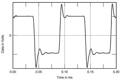
        I remember (loooooonnnggg ago) when I first scoped one of my Twin clones to see the overdriven waveform and saw something similar to this:


        the point being that leading edge overshot +V rails and ground (yes, saturating tube gets negative peaks) by 5% to 10% which is a lot.

        Nothing like the nice gentle rounded top waveforms drawn on many books, of course, but the real thing.

        Clamping diodes won´t let saturating plate go below ground (besides minuscule diode drop that is) so other plate won´t go above 2X +V (see saw action) so yes, under normal (loaded) conditions, diodes will clamp/chop that overshoot.

        In my book, they will also avoid many kV peaks which can and will appear if speaker gets disconnected or is much higher impedance than expected.

        Ho´s Ultimate Attenuator uses a one-size-fits-all 30 ohm load resistor.
        Fine for 16 ohm amps, not so sure about 4 ohm ones.

        A MOV "should" be rated around 3X +V , which is still safe, because if rated 2X it will be triggering all the time on overdrive.

        In this case rating to be considered is peak voltage, so 1.4X the AC value printed on it.
        Juan Manuel Fahey

        Comment


        • #34
          Originally posted by J M Fahey View Post
          A MOV "should" be rated around 3X +V , which is still safe, because if rated 2X it will be triggering all the time on overdrive.
          MOV's don't 'trigger', they have a very soft loading characteristic. A MOV rated at a 1mA level at 1.5x B+ would at worst just start passing a few mA at the very peak of that scope waveform. That MOV rating has quite a span for the 1mA level, so only the worst case part would pass a mA or so.

          Comment


          • #35
            Ok, then rate them so they pass MANY mA at, say, 1.5X Vpeak or they won´t do much "protecting" at all.

            In any case, I never use them, much prefer the very predictable and "automatic" reverse diode clamping action.
            Juan Manuel Fahey

            Comment


            • #36
              JMF, I'm not about advocating you use MOVs, just commenting on any misconceptions that arise.

              A MOV can be a good option for over-voltage protection of output transformers as its soft loading characteristic can usually be aligned to fit between normal anode working voltage levels and the likely design voltage stress rating of the winding. Luckily an OPT primary winding would be designed, manufactured and possibly even tested along the same lines as a power transformer, with respect to insulation system and creepage/clearance, as the working voltage of an OPT primary winding is often higher than mains AC (even for my 240Vac mains, and especially the rating to core). So as a ball-park, an OPT primary winding could be expected to have at least a 1.5 to 2kV withstand capability. If the MOV can exhibit a heavy loading resistance across the winding at the 1.5 to 2kV level then it is doing its job, noting that it would be progressively representing a lower and lower resistance if the winding had the energy to keep pushing its terminal voltage up towards that 1.5-2kV level.

              A good perusal of typical MOV V-I curves shows that there is usually a range of MOV models (eg. VAC ratings) that can fit the objective of not noticeably conducting at levels up to 1.5-2x B+, and heavily conducting at 1.5-2kV.

              I agree that the MOV 'design path' can be a bit too fuzzy for those that prefer tight tolerance protective actions, but note that most seem to live with using fuses.

              Ciao, Tim

              Comment


              • #37
                Originally posted by J M Fahey View Post
                In any case, I never use them, much prefer the very predictable and "automatic" reverse diode clamping action.
                The problem is that plate diode clamping relies on transformer action, and it can't clamp leakage inductance flyback at all. The clamping diode is always clamping one side to ground and it's the other side that is flying up at a bit less than B+ times 2, plus any leakage inductance kickback.

                Granted, the differences may be small in real world situations.

                One advantage for the TVS style clamps is that they're more abrupt than MOVs.

                Many amps have none of the above, and live long, happy lives.

                Sigh. Mother Nature is such a mother.
                Amazing!! Who would ever have guessed that someone who villified the evil rich people would begin happily accepting their millions in speaking fees!

                Oh, wait! That sounds familiar, somehow.

                Comment


                • #38
                  Good.

                  So far we are speaking words, it would be nice to put some numbers into it.

                  Please somebody find an OT datasheet showing rated primary inductance (many will state that) and leakage inductance ... I bet most will be silent, but maybe a few brave souls print it.
                  Probably some Hi Fi guys will.

                  I would not be surprised at finding leakage inductance is 10% or 5% of main inductance.

                  And then finding that although it IS there, (I have no doubt about that, only doubt is how much) , it probably is not enough to kill a mouse.

                  But let´s get some numbers first.

                  Energy almacenated in an inductor is straight to calculate .... same as energy in a capacitor is.
                  Then we´ll know whether we are facing a Lion or a furry kitty
                  Juan Manuel Fahey

                  Comment


                  • #39
                    I have had a go at putting some numbers to spike energy from a few fault scenarios in the linked article:
                    https://www.dalmura.com.au/static/Ou...protection.pdf

                    Hi-fi OT's were very informative of parasitic L & C values, mainly due to the Williamson amplifier's demands - the Partridge datasheets in particular (eg. links in https://www.dalmura.com.au/projects/Williamson.html). A few transformer players, like Patrick Turner, have progressed the design and measurement of those parasitics. But yes OT's in guitar amps could well show larger parasitic L, but also likely lower winding inductance.

                    Comment


                    • #40
                      I'm all for looking at numbers. Even where you don't know the underlying relationships and interactions, they can give you useful trends and projections.

                      First, a well designed hifi OT will have microscopically small leakage inductance. The "Goodness Factor" from the Golden Age of tube amplifers was simply the primary inductance divided by the leakage inductance. These were commonly 10,000 to 100,000.

                      These were made by very, very careful interleaving of layers. It is possible to make excellent estimations of leakage inductance by calculation based on numbers of turns and the physical arrangements of window size, winding width, and winding build height. It is possible to >maximize< leakage inductance by winding primary and secondary side by side, as you see in some power transformers; it's even more extreme in ferroresonant transformers with windings side by side and iron shunts between them. This is the degenerate case, and definitely not what you want in a signal transformer.

                      To minimize leakage, you intermix the wires. The extreme in this direction is to wind all wires multifilar. A bifilar OT primary is possible, and very useful for preventing pseudo crossover distortion from leakage causing issues in the handoff from one half cycle to the other in an AB pushpull. It would be ideal in terms of leakage for an OT to wind all of it multifilar, with the number of turns being just the secondary number of turns, but with maybe 25 primary wires wound side by side with the secondary turns, and then the many primary sections interconnected in series external to the winding. Aside from the practical impossibility of doing this, this winding style also maximizes interwinding capacitance, which may give other problems.

                      Back at leakage inductance, the math says that if you get a certain leakage for primary over secondary, the leakage is reduced by a factor of the square of the number of interfaces. Primary over secondary (or vice versa) is a factor of one. Split primary (or secondary) sandwiching the secondary (or primary) is two interfaces, and the leakage from the simple case is reduced by a factor of four. A split with three sections sandwiching two sections is four splits, and this leakage is reduced by a factor of sixteen over the simple one-interface case. This process keeps up until you can no longer do the physical work of winding the layers and splitting the windings into finer and finer sub sections, or until you get to multifilar.

                      So the question becomes what is your leakage inductance in that OT you have in your hand? You can measure it of course. But there isn't any good way to say how big it is as related to the primary inductance without either measuring it or knowing exactly how it was wound. In the early days of tube amps, guitar amps used much the same OTs as hifi stuff, as this was easy to get from the companies that made hifi stuff. Later, hifi and guitar amps diverged, and the rise of the MBA led to cheapening everything until the customers just would not buy them any more so when guitar amp makes had to start ordering special runs of OTs for just them, they started backing down on the interleaving to reduce cost. This led to some pretty bad OTs in both the sound and high leakage inductance, as the end result was one-interface winding.

                      The one-interface winding was common in some brands. Marshall was reputed to order off-the-shelf Radio Spares for a while. I have cut open some dead Marshall OTs and found single sections. It's likely to be the case in other brands as well. My amp-tech friend tells me that it's more common in his experience to have dead Marshall OTs. It's not clear that this is a causal link, but it's fun to specify.

                      Guitar amp OTs have lower primary inductance than hifi standard, as befits their lesser needs for low end, and most likely poorer interleaving. The exact numbers will vary a lot, depending on the size of the transformer's window and how it's wound, but it's hard to imagine a ratio of primary to secondary worse than 20:1, that giving you a 5% leakage number.

                      Guitar OTs also typically have smaller primary inductances. I've heard numbers of 20H to 50H for guitar OTs, but have not measured one in a loooooong time. Let's say for the sake of discussion that the OT in question has a primary of 40H and a factor of 2%. So the leakage inductance might be 800mH. That seems grossly too big to me. We could just as easily say it was 1% or 0.5%. So you'd get a couple of hundred millihenries.

                      From there, the energy is just E = 1/2*L*I squared.

                      But now we get down to the issue of what damage gets done. Nothing happens until the wire insulation gets punctured. Puncturing depends on voltage, not energy. Energy gets into play once a puncture has been made, and damage per puncture is proportional to energy. Even a much smaller inductance can generate a nearly unlimited voltage. The real limits on V = L*di/dt for generating a puncture is the winding self-capacitance. It limits the rate of rise and hence the voltage. My quick look just now at magnet wire insulation showed film strengths of between 50l0V and 2500V.

                      A lot depends on the details of where the voltage happens and what happens after the first puncture. Magnet wire mostly insulates between adjacent turns in layer wound coils. In random wound coils, physically adjacent turns may have large voltages between them, so the voltage stress may be both larger and vary from unit to unit.

                      The first puncture most likely does not kill the transformer, and one or a few punctures may not ever kill it. But any puncture of the layer insulation will happen at a point of high voltage stress, and like arcing on tube sockets - and for the same reasons! - further arcs will be easier to start at the position of a previous arc. So one arc is a question of voltage, not energy. The second through ten thousandth arcs are where the damage adds up.
                      Amazing!! Who would ever have guessed that someone who villified the evil rich people would begin happily accepting their millions in speaking fees!

                      Oh, wait! That sounds familiar, somehow.

                      Comment

                      Working...
                      X