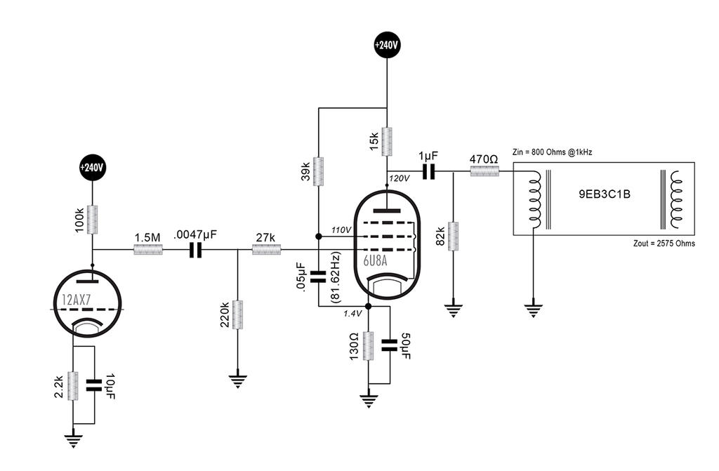
I'm working on a silvertone 1474 for a buddy of mine right now. One of the things we were talking about was that he took out the reverb unit because he didn't like it and doesn't use it. So there's an entire 6CG7 envelope not being used in the amplifier. This inspired me do something I've been wanting to do for a little while, which is design a ground up small signal pentode stage and a reverb drive circuit. This allows me to do both at once.
I first learned about this idea from the article I read here:
http://www.channelroadamps.com/articles/reverb_driver/
For the purposes of maintenance and efficiency, I limited the design around choosing from 9-pin pentode/triode tubes with 6V heaters that are in current production. I found datasheets for the following tubes:
6AW8A, 6AN8, 6GH8, 6BM8, and 6U8A. I chose a the 6U8A because it had plenty of current drive available for the tank I wanted to use, it was readily available, and the triode component had a little more gain available than some of the others for the recovery stage.
Here are the mutual characteristic curves, (the first showing plate curves with a screen voltage of 110V)

The tank I'm going to use is:
MOD 9EB3C1B
3-spring long decay • Input Impedance 800 Ohms, Output Impedance 2575 Ohms
Input Insulated/Output Grounded
Horizontal, Open Side Down Mounting Plane
Accutronics states that the nominal drive current for this input transducer as 3.1mA (just under 4.4mA peak). So, here's my question:
To limit the drive current from overloading and saturating the input coil, I was going to set the OVg1 plate current by adjusting the screen voltage so that the current through the load doesn't exceed the 4.4mA peak to peak from it's bias point. Correct?
For example, of one of the options I was considering. The existing circuit gives me supply voltage of 240V. With a screen voltage of around 80V, the plate current stays pretty constant until slope of the knee at around 11.5mA at OVg1. With a load of 22K and a bias of -1.5V, the output signal looks pretty linear with an input up to 2V P-P and a headroom of 3V P-P.
The quiescent current should be around 5.2mA and should max out to 8.2mA. With a driving source impedance of 22k and plenty of signal swing drive the coil at any frequency of interest, this is enough to approximate a constant current source, correct? did I miss anything or make any mistakes? (See load line and curves for 80V screen voltage below)

I first learned about this idea from the article I read here:
http://www.channelroadamps.com/articles/reverb_driver/
For the purposes of maintenance and efficiency, I limited the design around choosing from 9-pin pentode/triode tubes with 6V heaters that are in current production. I found datasheets for the following tubes:
6AW8A, 6AN8, 6GH8, 6BM8, and 6U8A. I chose a the 6U8A because it had plenty of current drive available for the tank I wanted to use, it was readily available, and the triode component had a little more gain available than some of the others for the recovery stage.
Here are the mutual characteristic curves, (the first showing plate curves with a screen voltage of 110V)
The tank I'm going to use is:
MOD 9EB3C1B
3-spring long decay • Input Impedance 800 Ohms, Output Impedance 2575 Ohms
Input Insulated/Output Grounded
Horizontal, Open Side Down Mounting Plane
Accutronics states that the nominal drive current for this input transducer as 3.1mA (just under 4.4mA peak). So, here's my question:
To limit the drive current from overloading and saturating the input coil, I was going to set the OVg1 plate current by adjusting the screen voltage so that the current through the load doesn't exceed the 4.4mA peak to peak from it's bias point. Correct?
For example, of one of the options I was considering. The existing circuit gives me supply voltage of 240V. With a screen voltage of around 80V, the plate current stays pretty constant until slope of the knee at around 11.5mA at OVg1. With a load of 22K and a bias of -1.5V, the output signal looks pretty linear with an input up to 2V P-P and a headroom of 3V P-P.
The quiescent current should be around 5.2mA and should max out to 8.2mA. With a driving source impedance of 22k and plenty of signal swing drive the coil at any frequency of interest, this is enough to approximate a constant current source, correct? did I miss anything or make any mistakes? (See load line and curves for 80V screen voltage below)


Comment