Ad Widget

Collapse

Announcement

Collapse
No announcement yet.

Cathode follower without elevated heater voltage

Collapse
X
 
  • Filter
  • Time
  • Show
Clear All
new posts

  • Originally posted by Chuck H View Post
    As I said, it happens to the best of us... Or at least me

    Some of those voltages do look questionable. The problem is identifying their location in the circuit. I know you've posted some of the actual tube lineup relative to gain stage progression, but maybe a primer now would be a good thing. Also, V1b and V3b are pretty clearly the cathode follower stages. It would be good to have the grid pin voltages for AT LEAST those.

    P.S. You're hanging in well. And I hope you're having some fun.
    Yes, tubes 1 and 3 are the cathode follower tubes. Tube 2 is actually first in the signal chain. I could just draw the voltages onto the schematic. That would probably make things easier. And thanks, yeah, its fun. I could just pay some dude to fix it. I coulda done that years ago when I realised it wasn't just some easy fix. It's still an option, but I'd feel like I cheated.
    Since I'm getting nothing at all out of the speakers now, and I was before the re-wire, I'm wondering if I might have somehow wired the wrong secondary wired from the Ot to the output jack when I removed the impedence selector. I'm pretty sure I checked it. I'm also pretty sure that oit would still make SOME kind of noise, regardless, but I'm basing that on nothing at all, really.
    Anyways, I'll try to measure the grid pins tomorrow. It will still be in reference to ground, right? And still DC? I also don't have a guitar right now cus that's undergoing a restoration, but I wired a pickup directly to a jack for testing purposes if I gotta plug something into the amp

    Comment


    • No need to plug anything into the input now. But that's a clever idea you had there. DC readings all around right now.

      Bias on the first stage and then the cathode voltage on the second cathode follower are probably worth questioning. One thing at a time. As we (and I hope that means more than you and I ) move along we'll get to why there's no sound from the speaker. I'm not a repair guy, but I have some mod and design chops. This amp, having worked before, and it's thread here will benefit from the considerable repair and troubleshooting skills that many of our frequent posters have.
      "Take two placebos, works twice as well." Enzo

      "Now get off my lawn with your silicooties and boom-chucka speakers and computers masquerading as amplifiers" Justin Thomas

      "If you're not interested in opinions and the experience of others, why even start a thread?
      You can't just expect consent." Helmholtz

      Comment


      • Originally posted by Chuck H View Post
        No need to plug anything into the input now. But that's a clever idea you had there. DC readings all around right now.

        Bias on the first stage and then the cathode voltage on the second cathode follower are probably worth questioning. One thing at a time. As we (and I hope that means more than you and I ) move along we'll get to why there's no sound from the speaker. I'm not a repair guy, but I have some mod and design chops. This amp, having worked before, and it's thread here will benefit from the considerable repair and troubleshooting skills that many of our frequent posters have.
        I think my best move right now, is to draw out a full schematic of what's actually in the amp and put all the voltages I've measured so far on it. That will give people a single point of reference, rather than having to read through the whole thread. There were also suggestions up there, that I hagven't got around to checking, so I'll make a to-do list of those.

        When I re-did the wiring, I mostly used the schematic and the drawings that were in the..."manual". (The sheet with the grid connections was missing, but I'm pretty sure those are all right) Or, I just cut the original wire and taped a label on it, saying where it connects. The only thing I did by assumption was the negative feedback wire from the output jack. I never bothered to label it, because I assumed it connects to the "hot" tab on the jack, since I assumed the other one is connected to ground anyways, just by being bolted to the chassis. I'm pretty sure my assumption was right, but since it was the only assumption I made, I need to check it. I get continuity to ground from either tab, but I assume that's just reading through the OT secondary from tab to tab, with no speaker plugged in. (I get about 0.3 ohms between those) They just look like regulat guitar jacks, so I assume there would be no earthly reason to connect the feedback wire to the other tab if it's grounded right there

        Comment


        • AHHH...While drawing out a proper schematic, I noticed a huge goof. SOMEONE - probably a burglar - wired one of the output jacks back to front, effectively shorting the output transformer secondary. I haven't put it right yet, but I think it's pretty safe to assume that that's where I screwed up.

          EDIT

          Okay, I fixed that and was still left with a dead amp...until I plugged in the footswitch and kicked it. The second channel is fine now, which simplifies things. In fact, I think it may even be cured of the original problem. I have no guitar to test with, but plugging in a pickup, I could crank the volume and tap the pole pieces with a screw driver, at volumes that would have had the amp spluttering and machine gunning before. So, I think the incorrectly wired cathode follower tubes WERE the original problem. The subsequent problem was my oopsie with the backwards output jack, in parallel with a correctly wired one, and now, I just have this problem with the clean channel, Which is probably just a result of all my poking around, or maybe one faulty preamp tube.
          I found some other parts that were way off what the schematic called for. The plate resistor on the first stage, is 460K, and the cathode resistor on that stage is 5.6k. An attempt to get more gain? The feedback resistor, which the schematic has at 5.6k, and the circuit drawing has at 6.8k, is 33k in the amp. Dunno what the thinking behind that was. More distortion again?

          Now I guess all those voltages I measured will have changed again, right?

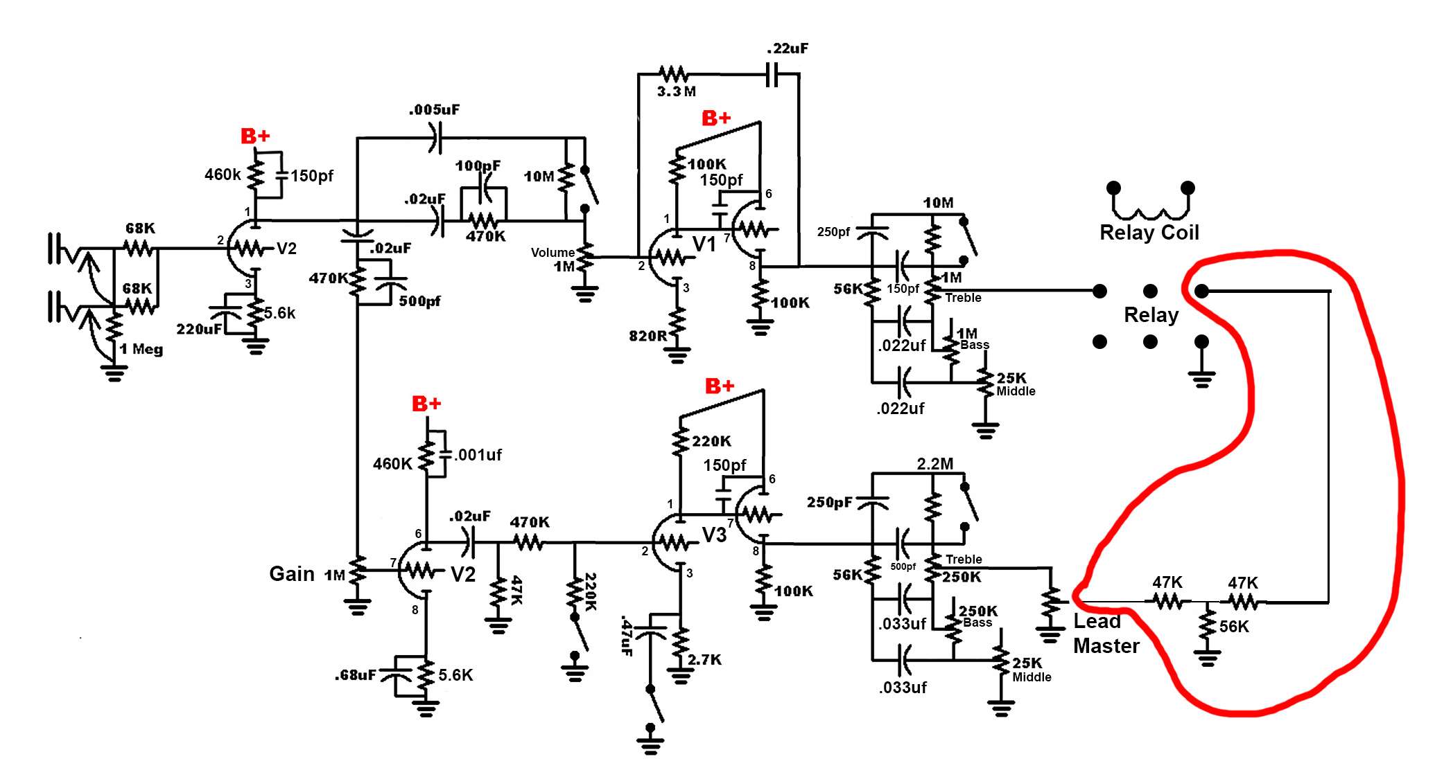
          Anyways...Here's what I got so far on that schematic. This is what is actually in the amp as of right now. I drew the whole relay and the coil, cus I want to include all the ancillary circuits and maybe save someone a headache in the future. Especially myself.
          Click image for larger version

Name:	preampCh1.jpg
Views:	1
Size:	133.5 KB
ID:	853535
          Last edited by Dark Mavis; 03-29-2019, 11:43 PM.

          Comment


          • Originally posted by Dark Mavis View Post
            AHHH...While drawing out a proper schematic, I noticed a huge goof. SOMEONE - probably a burglar - wired one of the output jacks back to front, effectively shorting the output transformer secondary. I haven't put it right yet, but I think it's pretty safe to assume that that's where I screwed up
            That would make it mighty quiet... the way a burglar likes it!
            If it still won't get loud enough, it's probably broken. - Steve Conner
            If the thing works, stop fixing it. - Enzo
            We need more chaos in music, in art... I'm here to make it. - Justin Thomas
            MANY things in human experience can be easily differentiated, yet *impossible* to express as a measurement. - Juan Fahey

            Comment


            • Originally posted by eschertron View Post
              That would make it mighty quiet... the way a burglar likes it!
              Yes, I need to beef up my security. Damn burglars. Anyways, I edited that last post to include what happened after I corrected the wiring

              Edit...there's a distinct possibility I just had the volume all the way down on the first channel. Need to check that.
              Edit. Nope. Clean channel silent. Nothing at all through the speaker. Surely that puts the problem nearer the output end of the channel than the input side?

              Comment


              • Originally posted by Dark Mavis View Post
                I found some other parts that were way off what the schematic called for. The plate resistor on the first stage, is 460K, and the cathode resistor on that stage is 5.6k. An attempt to get more gain?
                [ATTACH=CONFIG]53181[/ATTACH]
                I was looking back at post #41 to try and correlate tube number-names with circuit positions, and saw that both V2 cathodes were listed as 5.6K, so check the other side of it too.
                Like Chuck mentioned, the two CF stages seem to disagree too much with voltages. Both have same plate voltage and cathode resistor values, both have same voltages reported from previous plate (so should appear on grids). So it doesn't make sense that one would show 76V at cathode and the other, 37V. Double check those plate voltages feeding the CF grids.

                To recap, voltages listed in post #103, original schematic here: https://music-electronics-forum.com/...1&d=1553263142

                From what I gather of the resistance values given in post #41, this is the configuration:
                V1: upper 2nd stage and CF
                V2: 1st stage, upper and lower
                V3: lower 2nd stage and CF
                V4: mixer/FX send and FX return
                V5: reverb drive and pickup
                V6: Phase Inverter
                Originally posted by Enzo
                I have a sign in my shop that says, "Never think up reasons not to check something."


                Comment


                • Originally posted by g1 View Post
                  I was looking back at post #41 to try and correlate tube number-names with circuit positions, and saw that both V2 cathodes were listed as 5.6K, so check the other side of it too.
                  Like Chuck mentioned, the two CF stages seem to disagree too much with voltages. Both have same plate voltage and cathode resistor values, both have same voltages reported from previous plate (so should appear on grids). So it doesn't make sense that one would show 76V at cathode and the other, 37V. Double check those plate voltages feeding the CF grids.

                  To recap, voltages listed in post #103, original schematic here: https://music-electronics-forum.com/...1&d=1553263142

                  From what I gather of the resistance values given in post #41, this is the configuration:
                  V1: upper 2nd stage and CF
                  V2: 1st stage, upper and lower
                  V3: lower 2nd stage and CF
                  V4: mixer/FX send and FX return
                  V5: reverb drive and pickup
                  V6: Phase Inverter

                  Yeah, in the actual amp, both cathode resistors on V2 are 5.6k. Both plate resistors are 460k. In the schematic I got with the amp, both those plate resistors are 220k. The cathode resistor on pin 3 is 1.5k and on pin 8 it's 2.7k. I haven't got around to checking all the values and drawing out a full schematic of what's actually there, yet. Just the clean channel so far.

                  By "Upper", I take it you mean the channel that's on top, in the schematic? If so, then yes, that configuration is correct. I've been labelling the tubes and pin numbers on the new diagram I'm drawing up

                  Comment


                  • Okay, here's what I got so far. Really not sure what's up with those 3 resistors. They're not on the schematic at all, but they are on the circuit board layout drawings. It looks like they're just there to adjust the output of the channel down a bit.
                    I can understand why this amp has always had a problem. The "manual" is extremely vague and unclear. On the schematic, the center tab of the pot that's labelled as "lead master" on the actual amp, and has a dozen different names throughout the manual, is connected directly to the relay. It looks for all the world like this design went through several versions, but whoever was revising the "manual" left in a lot of stuff from earlier versions. I would not want to be building an amp from one of this guy's kits.
                    anyways...here's the pic:
                    Attached Files

                    Comment


                    • Yup. The schematic appears to be either wrong, or from an earlier/newer version.
                      This is what I got so far:

                      There's a whole lot of different stuff going on over by the reverb pot. I found that the .22 cap on the plate of the first stage of V4, was broken loose on one side. I haven't found anything yet that explains the dead clean channel though

                      Edit. Here's the original schematic:
                      Last edited by Dark Mavis; 04-01-2019, 01:49 AM.

                      Comment


                      • I'm confused by the way you have the relay drawn. If it's as I'd read it (middle pin selects either side) then the clean channel has no path out.
                        ...not saying that's what's going on, though.
                        If it still won't get loud enough, it's probably broken. - Steve Conner
                        If the thing works, stop fixing it. - Enzo
                        We need more chaos in music, in art... I'm here to make it. - Justin Thomas
                        MANY things in human experience can be easily differentiated, yet *impossible* to express as a measurement. - Juan Fahey

                        Comment


                        • Originally posted by eschertron View Post
                          I'm confused by the way you have the relay drawn. If it's as I'd read it (middle pin selects either side) then the clean channel has no path out.
                          ...not saying that's what's going on, though.
                          Yeah, That might be why no clean channel. I keep telling myself it can't be, cus at no point did two wires break off the relay at once, so I dunno how I could have got them crossed. I left the wiring on the relay untouched, but occasionally, a wire broke loose as I worked. But only one at a time.
                          I'd also assume that the relay is wired so that each of the middle tabs, is connected to either each of the left ones, or each of the right ones. I literally just drew it as it's arranged in the amp, except the coil connections, which I moved off out of the way

                          Edit...It's GOTTA be a mistake I made. Possibly years ago. I don't even remember the last time I opened the amp or heard a note out of it

                          Edit:
                          THIS is what I'd expect. For the contacts inside, to either make the connections shown in blue, or those shown in red, like prettly much every other douple pole relay.
                          Click image for larger version

Name:	relay.jpg
Views:	1
Size:	6.5 KB
ID:	853544
                          If so, I think I somehow got my wires crossed without realising. Or maybe the burglar did it when he was swapping the wires on that output jack
                          Last edited by Dark Mavis; 04-01-2019, 02:08 AM.

                          Comment


                          • Just to be sure, double check the pin-out from a datasheet for the relay part number or see if there is a drawing on the relay itself.
                            The relay pin-outs are not always what we'd expect, sometimes they are quite odd.
                            Originally posted by Enzo
                            I have a sign in my shop that says, "Never think up reasons not to check something."


                            Comment


                            • Originally posted by g1 View Post
                              Just to be sure, double check the pin-out from a datasheet for the relay part number or see if there is a drawing on the relay itself.
                              The relay pin-outs are not always what we'd expect, sometimes they are quite odd.
                              Ah, it's actually not how I thought. This is from the datasheet, so maybe the wiring is right

                              Click image for larger version

Name:	relay2.jpg
Views:	1
Size:	15.5 KB
ID:	853545

                              Comment


                              • Soldering iron died. So...while I wait for a replacement, I'll finish the diagram and then measure every voltage and resistance mentioned in the thread so far, and add them to the diagram. I THINK the original problem - the one the amp always had - is fixed now, since one channel seems to work normally.
                                I think the relay is wired correctly. If it switches the way the datasheet seems to show, then it looks right. Depending on the relay's position, one channel is connected to the next stage, while the other is connected to ground at a point before the second stage. I'll draw the internals of it onto the diagram for clarity

                                Comment

                                Working...
                                X