Ad Widget

Collapse

Announcement

Collapse
No announcement yet.

Interleaving pattern in this blackface Super Reverb OT

Collapse
X
 
  • Filter
  • Time
  • Show
Clear All
new posts

  • Interleaving pattern in this blackface Super Reverb OT

    -
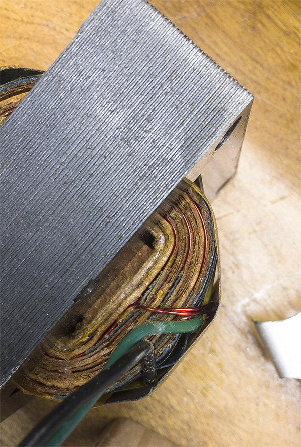
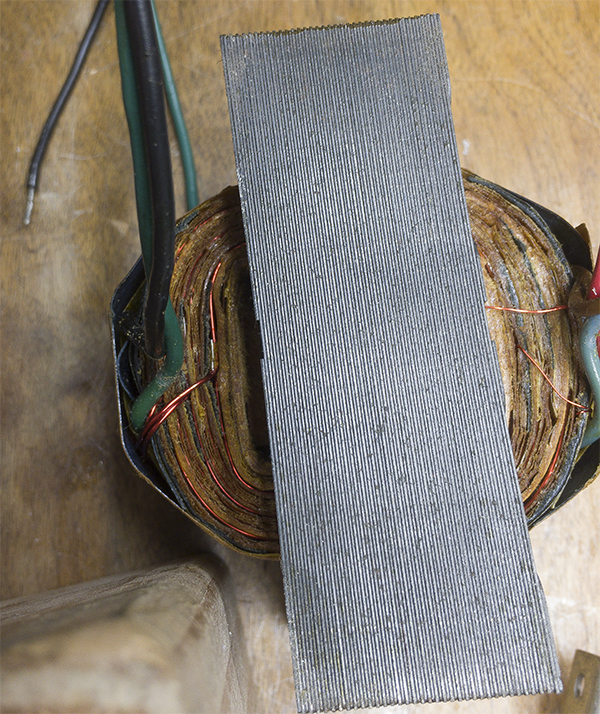
    I found myself in the possession of several NOS Super Reverb (and other) output transformers manufactured by Schumacher. These things are in unreal condition, and I wanted to take a look at the winding of one of them.
    I took some photos which seem to show the winding layers pretty clearly and was wondering if any of you can make out what the interleaving pattern is from these. I guess I was a bit surprised to see what looks like any interleaving at all.

    If I have a 50% chance of guessing the right answer, I guess wrong 80% of the time.

  • #2
    Schumacher typically winds alternate layers of primary, split in 3 or 4 sections , intercalated with secondary windings, as in 1/4 ... secondary ... 1/4 ... secondary ... 1/2 ... secondary OR 1/4 ... sec ... 1/4 ... sec ... 1/4 ... sec ... 1/4
    Two 1/4 in series make one full plate to CT winding.
    In the case of the Super Reverb, you have 3 secondary windings, same turns, same diameter, connected in parallel to make out the 2 ohm secondary which otherwise would require very thick, too hard to wind wire.

    Looks very elaborate and expensive but if you have the machine set up with 2 different advance screws or gears and can switch back and forth (setting up exact wire advance is somewhat time consuming, madness to reset on every other layer) then winding can be very fast.
    Juan Manuel Fahey

    Comment


    • #3
      No content on original question, but a comment on winding machines.

      Change gears, advance screws, and the like on winding machines are very time consuming to set up, as JM notes. However, in today's world, you can buy a controller that converts machining instructions (g-codes) to machine movements for as little as $10 (Arduino works, Raspberry Pi is more than adequate and only US$35), motor controllers for US$1.00 to US$30, and stepper motors for US$5-$50 depending on size.

      The world of 3D printers and DIY CNC mills and lasers has given us the cheap hardware to do any formerly picky mechanical task at low cost. I first flirted with this back when I was thinking about pickup winders. There is a world of DIY pickup winding similar to the ones for DIY amps and DIY effects where there are single-unit makers, few-unit hobbyists, semi-commercial cottage proprietors, and commercial outfits. And there is the requisite group of mystic gurus who sell a few secret-sauce units with good reputation. I surmised a turning axis on one stepper motor, a wire feed across the pickup with another pickup, and canned programs for making any pickup layup you want, and then doing it again.

      The big issues in pickup world seem to revolve around the differences between random/jumble wound pickups and layer-wound. With automation of the actual winding either way is easy. It goes further. If you make wire feed sensors to sense how a "guru" winds a magic pickup, you can then replay that winding any time you want.

      OK, back to the question.

      Amazing!! Who would ever have guessed that someone who villified the evil rich people would begin happily accepting their millions in speaking fees!

      Oh, wait! That sounds familiar, somehow.

      Comment


      • #4
        True, today you can have a PC controlled advance screw, no need to touch the main winding one, just count itsb turns, and adjust for any wire diameter in a jiffy.

        My comment refers to what Schumacher was doing , **for a competitive price** , 60 or more years ago ... which was obviously through some mechanical solution.
        Juan Manuel Fahey

        Comment


        • #5
          Interesting point about the 3 secondary winds in parallel to get the 2 ohm output. Makes me wonder if they used a more universal winding configuration with 4,8, and 16 ohm secondaries connected in parallel so they could use the same OT for several applications.
          If I have a 50% chance of guessing the right answer, I guess wrong 80% of the time.

          Comment


          • #6
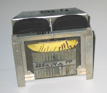
            World Class OTs for highest Audiophile performance, I mean the REAL one, no snake oil at all, are wound with the maximum interleaving possible: each and every layer is wound independently , alternating primary and secondary, all ends brought out separately, so they can be mixed and matched at will, you end up with *any* primary impedance, *any* secondary one at will, just do the math and connect windings as needed.
            Mr Turner from Australia has forgotten more about transformers than others will ever learn.

            This is but one page showing some of his products:
            http://www.turneraudio.com.au/for-sa...nsformers.html

            Just one example:
            by the way, he hides nothing, the whole transformer recipe is published ... so you "only" need to follow it
            OP1.
            Weight 7.4Kg, oa size 176mm x 132mm x 138mm.1 pair available.

            OP1-4-12-08

            PP UL or CFB or triode, 130W AB1, 4 x 6550, 3k1 : 5r5, Ea = +500V, Iadc = 150mA, 17W class A.

            SE CFB, SEUL, +air gap, 45W A1, 4 x 6550, 6 x EL34, 775r : 5r5, Ea = +320V, Ia = 350mA.

            SE Triode, +air gap, 35W, 4 x 6550, 6 x EL34, 775r : 5r5, Ea = +365V, Ia = 310mA.

            Primary = 1,496t x 0.45mm Cu dia, 11 layers 136tpl.

            Secondary = 12 layers 63t of 1.0mm Cu dia, Ns = 63t or 126t. ZR = 564 : 1 or 140 : 1.

            PP Interleaving = 11P x 12S,

            P-S insulation = 0.22 Nomex.

            Core = T52, S52, L76, H28mm.
            So he offers 11 separate Primaries, 12 separate Secondaries, wound S-P-S-P .... P-S ... 46 pigtails for your pleasure.

            In that page he also offers others:


            Notice no cheapo EI cores nor snowflake Toroids; all are C cores and with enough gap that they are *designed* to stand enough DC current to build large single ended amplifiers.

            Large in this context meaning >8 or 10W RMS, using parallel KT88, 2A3, etc.
            Juan Manuel Fahey

            Comment


            • #7
              I love that dude’s site. He has some nice info on amplifier compensation as well. Seems to be a big fan of running the LTP from a +\- supply with bipolar CCS in the tail as well. Can’t blame him for that.
              If I have a 50% chance of guessing the right answer, I guess wrong 80% of the time.

              Comment


              • #8
                “Snowflake toroids” HA!
                If I have a 50% chance of guessing the right answer, I guess wrong 80% of the time.

                Comment

                Working...
                X