Ad Widget

Collapse

Announcement

Collapse
No announcement yet.

PPIMV improvement

Collapse
X
 
  • Filter
  • Time
  • Show
Clear All
new posts

  • PPIMV improvement

    I never liked the PPIMV circuits for the obvious reasons. With the amps they're intended for you basically just get PI clipping instead of power tube clipping. And no PI circuit I'm aware of is known for it's good clipping. Sooo...

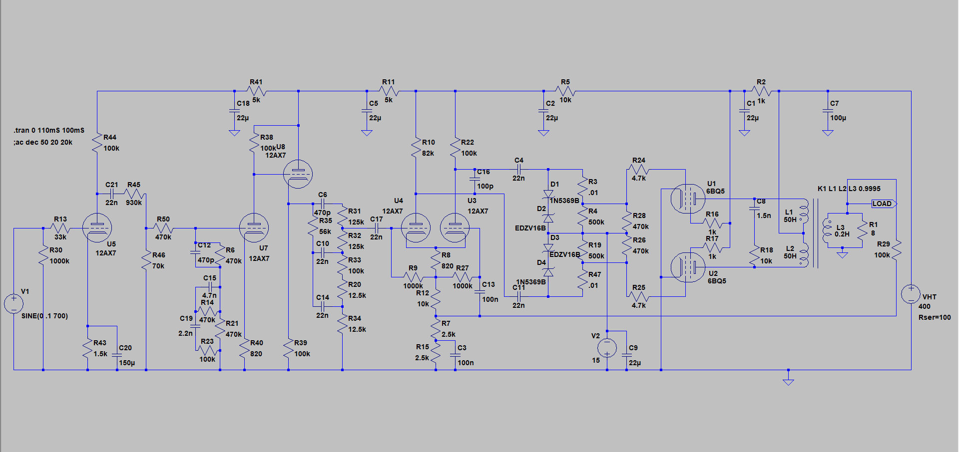
    Sort of like the the Paul Ruby mod, but inverse. Use a zener to clip the positive swing a volt above the bias voltage. That way when you turn down the master the diode takes over the signal clamping duties.

    The circuit shown below is just a plexi Marshall type preamp into an el84 power amp (the weird circuit behind the second triode is a simulation of the parallel channels load affect). But of course you could do this with any power tubes by valuing the zeners according to measurements taken with your meter.

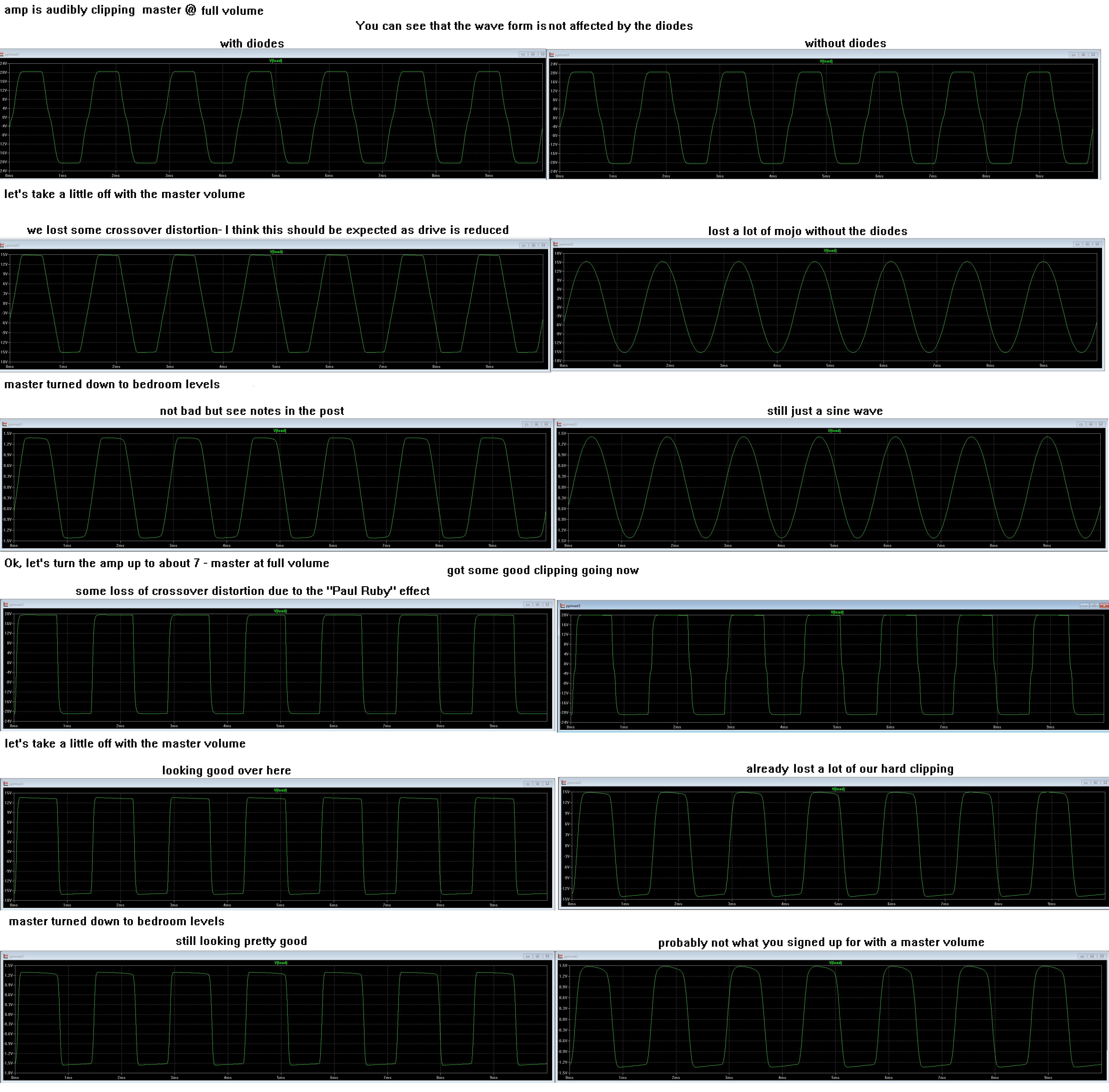
    One hitch I came across was that the clamping alone wasn't sufficient once the master was down and the peak to peak drive signal to the power tube grids started to approach the bias voltage. At that point the amp starts operating nearer class A and the negative swing on the PI signal begins to show up. So I used another zener to clip the negative swing at that threshold. This does implement a little of the "Paul Ruby" affect and mitigate some crossover distortion. So the absolute master full up, stock amp tone is affected a little by a reduction in crossover distortion. In the circuit below the value for the zener on the negative swing is 51V. If you really only want to use the master for heavily clipped tones it can be valued larger for less of an affect on the stock tone. Though I don't think the loss of a little crossover distortion should be objectionable for most players.

    Another benefit to the zeners and the preserved signal clamping is that it greatly improves the taper of the master volume function. The range of volume across adjustment is much more even whereas without the diodes most of the useful adjustment is below about three on the knob.

    Sorry that the picture is a little low res. It's a cut and paste of LTSpice images. Hopefully you can zoom it if necessary to see the images.

    Attached Files
    Last edited by Chuck H; 02-23-2020, 05:16 PM.
    "Take two placebos, works twice as well." Enzo

    "Now get off my lawn with your silicooties and boom-chucka speakers and computers masquerading as amplifiers" Justin Thomas

    "If you're not interested in opinions and the experience of others, why even start a thread?
    You can't just expect consent." Helmholtz

  • #2
    I fooled with that sort of thing a while back. I put a 1N4007 to ground right after each PI coupling cap to clip the positive side of the PI signal once it got about a volt over the bias voltage. The problem I encountered was that the speakers would drive the output signal wild at lower output levels. I gave up on it before I tried the zeners.
    Attached Files

    Comment


    • #3
      Yep. That's basically the same circuit, really. The difference is that I'm shunting positive swing over bias voltage to the bias supply so I don't need the extra inverse diode for the negative voltage being shunted to the bias supply. Only a difference in implementation. I think the function is just the same. Bad news about the instability. Something to do with the circuit being in the feedback loop I'm sure.?. Interesting that the simulations don't show any trouble. I'm glad you posted because this might save some other reader some trouble before this is further explored. Perhaps it's only good with lower NFB at lower master settings.?. The NFB switching in your schematic attempts to maintain a typical feedback ratio when the output is reduced by the master circuit. Were you doing this with your initial testing when you experienced the instability?
      Last edited by Chuck H; 02-24-2020, 12:24 AM.
      "Take two placebos, works twice as well." Enzo

      "Now get off my lawn with your silicooties and boom-chucka speakers and computers masquerading as amplifiers" Justin Thomas

      "If you're not interested in opinions and the experience of others, why even start a thread?
      You can't just expect consent." Helmholtz

      Comment


      • #4
        Ok... I did some more simulations. I modified one of my test circuits to be very much like yours and tried like hell to adjust it to be unstable, but I just couldn't get it to act funny. Then it occurred to me that you REALLY don't want any impedance on your bias supply in this circuit. Since some bias supplies actually do have a small impedance of, say 5k to 25k because of how they are arranged I added a 10k resistor in series with the bias supply. NFB ratio seemed to have little affect on it.

        Do you remember if your bias supply has any resistance between the filter caps and the output? And does THIS look like what you heard

        Attached Files
        Last edited by Chuck H; 02-24-2020, 01:35 AM.
        "Take two placebos, works twice as well." Enzo

        "Now get off my lawn with your silicooties and boom-chucka speakers and computers masquerading as amplifiers" Justin Thomas

        "If you're not interested in opinions and the experience of others, why even start a thread?
        You can't just expect consent." Helmholtz

        Comment


        • #5
          I only tried it with the two 1N4007s that clip the positive side. I like that arrangement because the 1N4007s don't have any effect when the thing is turned clear up. It also doesn't matter what the bias voltage is, so I don't need to find a particular zener voltage. It did a real nice symmetrical clip at the output with a dummy load, but when I used a guitar and the speakers, there were spikes all over the place. That doesn't mean that it didn't sound good and it did a real good AC/DC at only a couple of watts using preamp clip and just a little PI clip. A lot of PI clip did not sound very good to me and I didn't pursue it.

          I used the stock Marshall board with the usual bias circuit. I may have changed some values, but the topology was still the same. I don't think I had any resistance between the resistor strings and the second bias capacitor, but it's entirely possible in all the confusion. I just tacked resistors in series with the stock 100K NFB resistor to get the ratios at lower outputs and I don't think I tried any setting without the modified NFB. I do know that the presence always worked at any output level.
          Attached Files

          Comment


          • #6
            Ok. Thank you. So the impedance of your bias circuit would be the supply capacitor impedance. So much for that theory. I'll run some tests later replacing the load resistor with a simulated speaker load and see what happens. But I guess that's getting into some real imperfect simulations at that point and real world testing (like you've already done) start to make more sense.

            On another note I think your scenario with the diode referenced to ground is smarter because it tracks the bias regardless. While considering the circuit as you describe your testing I had an aha moment. It occurred to me that a zener will bias to the -V and track just the same as a standard diode. So why not use a single zener referenced to ground from each PI output. Much simpler circuit and does all the same things. So I tested this in the simulations and it really worked well. Obviously because of your experience with instability it'll need to go to the bench before I really know anything.

            Attached Files
            Last edited by Chuck H; 02-24-2020, 02:15 PM.
            "Take two placebos, works twice as well." Enzo

            "Now get off my lawn with your silicooties and boom-chucka speakers and computers masquerading as amplifiers" Justin Thomas

            "If you're not interested in opinions and the experience of others, why even start a thread?
            You can't just expect consent." Helmholtz

            Comment


            • #7
              I don't know how to interpret those oscilloscope waves. Nor can I imagine what effect those zeners have there. I only know that they are 82V / 5W.
              What is the objective explained in musical terms? Thanks!

              Comment


              • #8
                I think it's a SS PI output clipper before a post PIMV meant to emulate power tube input clipping caused by grid conduction, which would be prevented by the signal reduction caused by the MV.
                - Own Opinions Only -

                Comment


                • #9
                  I tested that system in an newly built amp with a JTM45 style preamp and 2xEL84 fixed bias with master volume. I have made two 80V zener strings adding two diodes of different voltages in series.
                  With the volume (bright channel) at max loses a lot of volume with the same master setting, generates an extra over-distortion and sounds thin and crushed. This effect is maintained gradually decreasing until approximately 3.5 in volume.
                  That voltage (80V) may not be the most appropriate but in any case that's the trend.
                  In my view, the phase splitter itself is already an impressive harmonic generator. No additives needed.
                  Thanks for the idea.

                  Click image for larger version

Name:	trtr.jpg
Views:	1
Size:	103.0 KB
ID:	856936

                  Comment

                  Working...
                  X