Ad Widget

Collapse

Announcement

Collapse
No announcement yet.

Dual bias supply

Collapse
X
 
  • Filter
  • Time
  • Show
Clear All
new posts

  • Dual bias supply

    I'd like to be able to set the bias separately on my two output tubes.
    I've looked at Fender's CBS balance circuits but they all use some strange
    pot with an extra tap. I've seen other amplifiers which balance things
    through the cathodes.

    I started with this 'Marshall' bias supply :
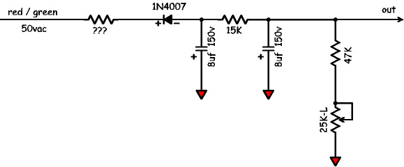


    I've tried different ways of splitting this into two separate bias sources and
    have come up with the following (the resistor values may need adjusting) :
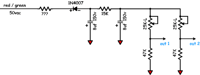


    Will this work ? I realise that the circuit will draw twice as much as the
    previous one but it's so little that I don't think it's a problem.

    Thanks,

    Paul P


    -
    Attached Files

  • #2
    No, they will interact because either one will pull their common point up and down.

    I realize it is just an example circuit, but get rid of those 8uf caps and use something substantial like 47uf or 100uf. 100v.

    The trick is to duplicate everything to the right of the diode in the first drawing. The diode and its first filter make the raw supply that both draw from. Then EACH supply gets its own 15k, its own second filter, and the rest. There will be two bias supplies from the same common raw source, as opposed to one dual supply.

    The current draw is negligible.
    Education is what you're left with after you have forgotten what you have learned.

    Comment


    • #3
      Thanks Enzo, now I can get some sleep. This circuit has been bothering
      me all evening.


      Paul P


      -
      Attached Files

      Comment


      • #4
        Yes.

        I don't know how appropriate your resistances are to your needs. But you can tweak them. Right now if I assume 60v at the rectifier, the bias will adjust between about 50v and 45v.
        Education is what you're left with after you have forgotten what you have learned.

        Comment


        • #5
          Looks overly complicated to me.

          I just like sc's one. http://www.soundcitysite.com/sc_webpages/sc_120_1.jpg Ok it interacts, but soo litle!

          Comment


          • #6
            I suppose that works too, but I prefer more filtering than that single cap on the raw supply.

            The difference betwen the two methods is three resistors, plus my two caps. I'd add caps to the wipers on the SC were it mine.

            And those wipers break a rule I have of never relying on the wiper of the trim pot for the bias feed. I always wire the pot as a variable resistor. REason is that if the wiper fails and it is the bias feed, the tubes lose all bias. if it is wired as a variable resistor as in the first example, then a dead wiper just leaves the pot at the coldest setting.
            Education is what you're left with after you have forgotten what you have learned.

            Comment


            • #7
              What kind of current can the bias tap on a power transformer supply ? It
              doesn't seem to be stated in any specs I've looked at.

              I'd like to individually bias two 6v6's which need anything from -26vdc for
              a 6G3 Deluxe to -35vdc for a blackface Deluxe Reverb. The more range
              I want from my bias circuit the more current I need at one end and the
              less I need at the other. So I need to know what is a reasonable maximum
              current that can be supplied by a bias tap (50vac in my case with an
              Allen PT) as well as the minimum bleeder current needed for proper
              operation of the circuit.

              For example, one set of values in the circuit gives an output that varies
              between -30 and -40vdc with .5ma to 1ma in each branch. Another set
              gives me -25 to -45vdc at .8ma to 5ma each branch.

              Paul P

              Comment


              • #8
                No current flows into the grids, the only current needed from the transformer is whatever the voltage divider resistors themselves draw. In the case of 15k, 47k, and 25k, that is 87k across for example 60v. Less than 1ma. Turn that 25k pot to zero and we have 62k, so again at 60v, that is still less than 1ma.

                What is the raw voltage you are starting with at the diode?

                REmember the ratio is what matters in the voltage divider, not the values. If the current is too high, raise the resistor values but keep their ratios.

                And for given the raw voltage, if the resulting bias is too high, don't reduce the voltage by dragging it down harder, just raise the 15k to drop the range.
                Education is what you're left with after you have forgotten what you have learned.

                Comment


                • #9
                  The difficulty I have is in juggling the interaction between the range resistor and
                  the dividing resistors without knowing where the limits are regarding too much
                  current draw or too little. My transformer has a "50v bias tap" no current specified
                  (why is it never specified ?).

                  Say I want the lowest value for my adjustment to be -25v. I achieve this by having
                  the range resistor and the next one equal (the bias is taken between the two) so in
                  the original example I could use the 15k resistor and then replace the 47k with
                  another 15K resistor. When the variable resistor is set to zero, I get -25v
                  between the two resistors. This will be at 50v/30K = 1.7ma. There are two branches
                  so the total draw on the PT bias tap will be a maximum of 3.4ma. Is this too much ?
                  My transformer is supposed to be compatible with a deluxe reverb so it should be good
                  for at least 2.5ma (50v/20K) at 50v. But how much more ?

                  At the other end of the adjustment range I play with the ratio between the second
                  resistor and the pot. Say I want the highest value for my adjustment to be -45v.
                  I have to set things up to drop 5 volts across the range resistor leaving 45 after
                  that with the variable resistor set to max. Keeping the values just mentioned
                  I can get this with the two 15k resistors plus a 150K pot. But at a current
                  of less than 0.3ma. Is this too little ? I think I read somewhere that you need
                  a certain amount of current for a voltage divider to work properly ? And if
                  I want to go lower than the 3.4ma needed to get -25v at the low end of the
                  adjustment range I'll get even lower current than 0.3ma at the -45v end.

                  Paul P

                  Comment


                  • #10
                    They don't bother to spec the current because bias supplies don't hardly draw any. A handful of ma's won't tax the winding. 10ma out of a 50v winding is half a watt. If it were a winding to power a string of relays or something, then we would spec it. For example in jukeboxes, the PT handles not only the amplifier, but also 24v supplies for the motors in the unit.


                    Voltage dividers don't need current, though zeners do. But we are not using zeners for anything here. In op amp circuits where they need a 4.5v reference with 9v rails, a pair of 100k does just fine. Look at most any effects pedal.

                    Since it is a part of the B+ winding, I suppose there could be some sagging with B+ load. But that is why we use a nice hefty first filter cap after the diode. And that diode itself helps shield the thing from sags to a degree.

                    The winding hold up under the range of a single bias supply, the added couple ma from the second divider is not an issue for it.

                    I wouldn't make it with something like 1 meg resistors since we might wind up with too long a charging time for the filters.
                    Education is what you're left with after you have forgotten what you have learned.

                    Comment


                    • #11
                      Thanks again Enzo, you've been most helpful.

                      This was the last loose end of my amp design. Now I can start building
                      the thing (well as soon as I clean up the mess in the shop/garage).

                      Paul P

                      Comment


                      • #12
                        Ah yes, the garage. I have one of those. Every now and then I go out there and poke around in all the boxes and piles, and once in a while I find some slip of paper or transistor with a missing leg or something and throw it out and feel oh so proud of my accomplishment.
                        Education is what you're left with after you have forgotten what you have learned.

                        Comment


                        • #13
                          Here's the circuit with values that, if I've computed things properly, will
                          provide bias voltages between approximately -45vdc and -25vdc, from a
                          50 vac bias tap. The maximum current draw for the entire circuit, which
                          happens when both halves are set to -25vdc, is a bit over 3ma. The
                          minimum draw, when both halves are set to -45vdc, is around 1.5ma.


                          Paul P


                          -
                          Attached Files

                          Comment

                          Working...
                          X